
Method for managing device and solid state disk drive utilizing the same

Inactive Publication Date: 2010-12-30
MEDIATEK INC
View PDF24 Cites 156 Cited by
  • Summary
  • Abstract
  • Description
  • Claims
  • Application Information

AI Technical Summary

Benefits of technology

[0045]While the invention has been described by way of example and in terms of preferred embodiment, it is to be understood that the invention is not limited thereto. Those who are skilled in this technology can still make various alterations and modifications without departing from the scope and spirit of this invention. Therefore, the scope of the present invention shall be defined and protected by the following claims and their equivalents.

Problems solved by technology

Although the MLC is more area efficient than the SLC, one drawback of using the MLC is its relatively short operating lifespan.

Method used


Image

  • Method for managing device and solid state disk drive utilizing the same
  • Method for managing device and solid state disk drive utilizing the same
  • Method for managing device and solid state disk drive utilizing the same

Examples


Embodiment Construction

[0023]The following description is of the best-contemplated mode of carrying out the invention. This description is made for the purpose of illustrating the general principles of the invention and should not be taken in a limiting sense. The scope of the invention is best determined by reference to the appended claims.

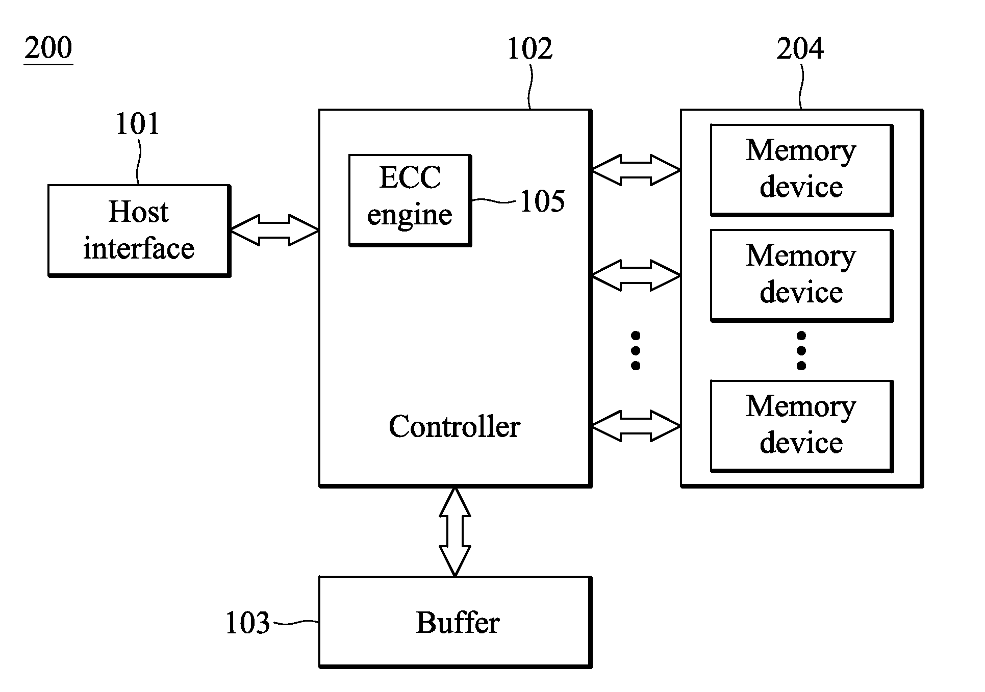
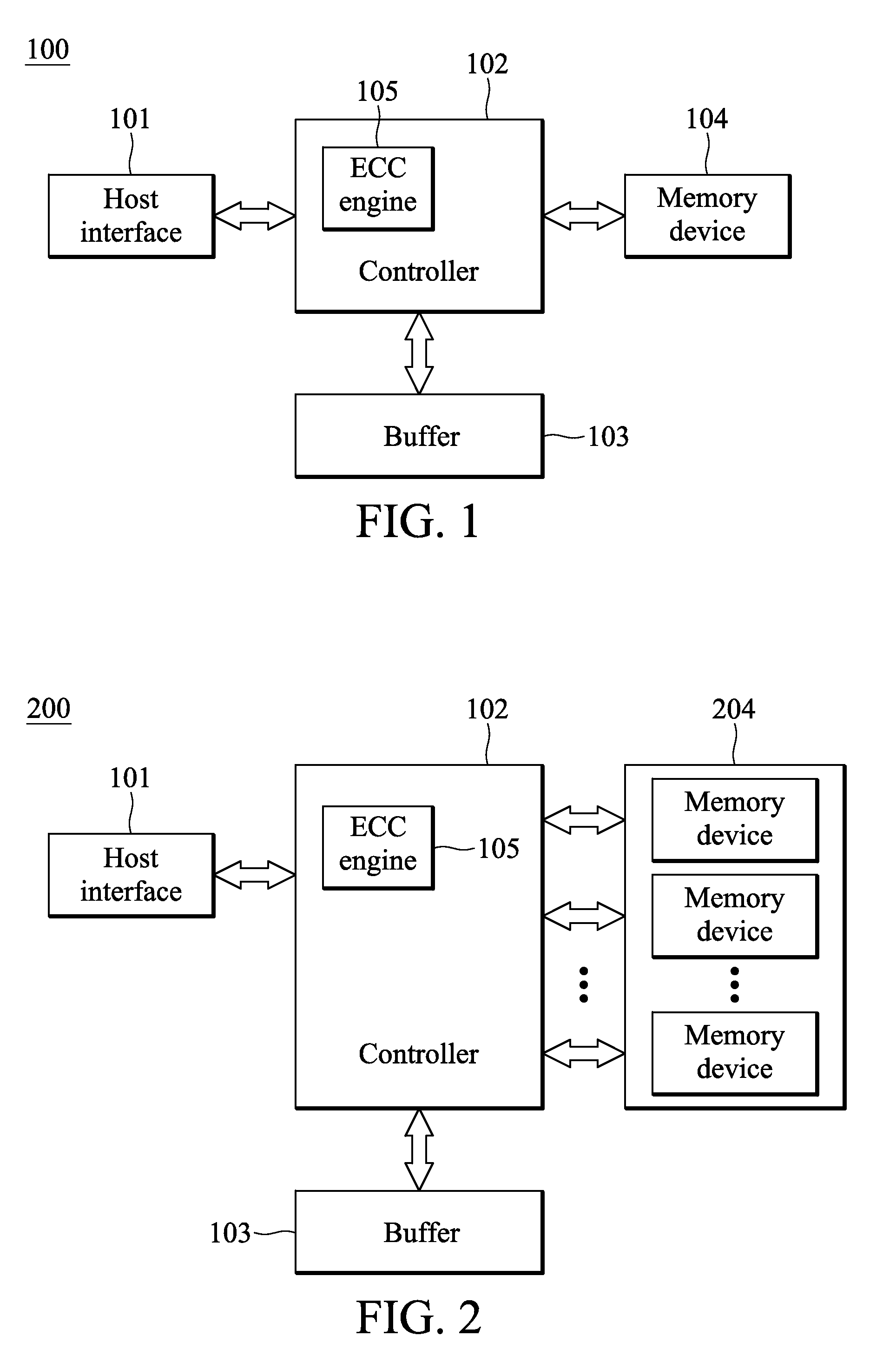
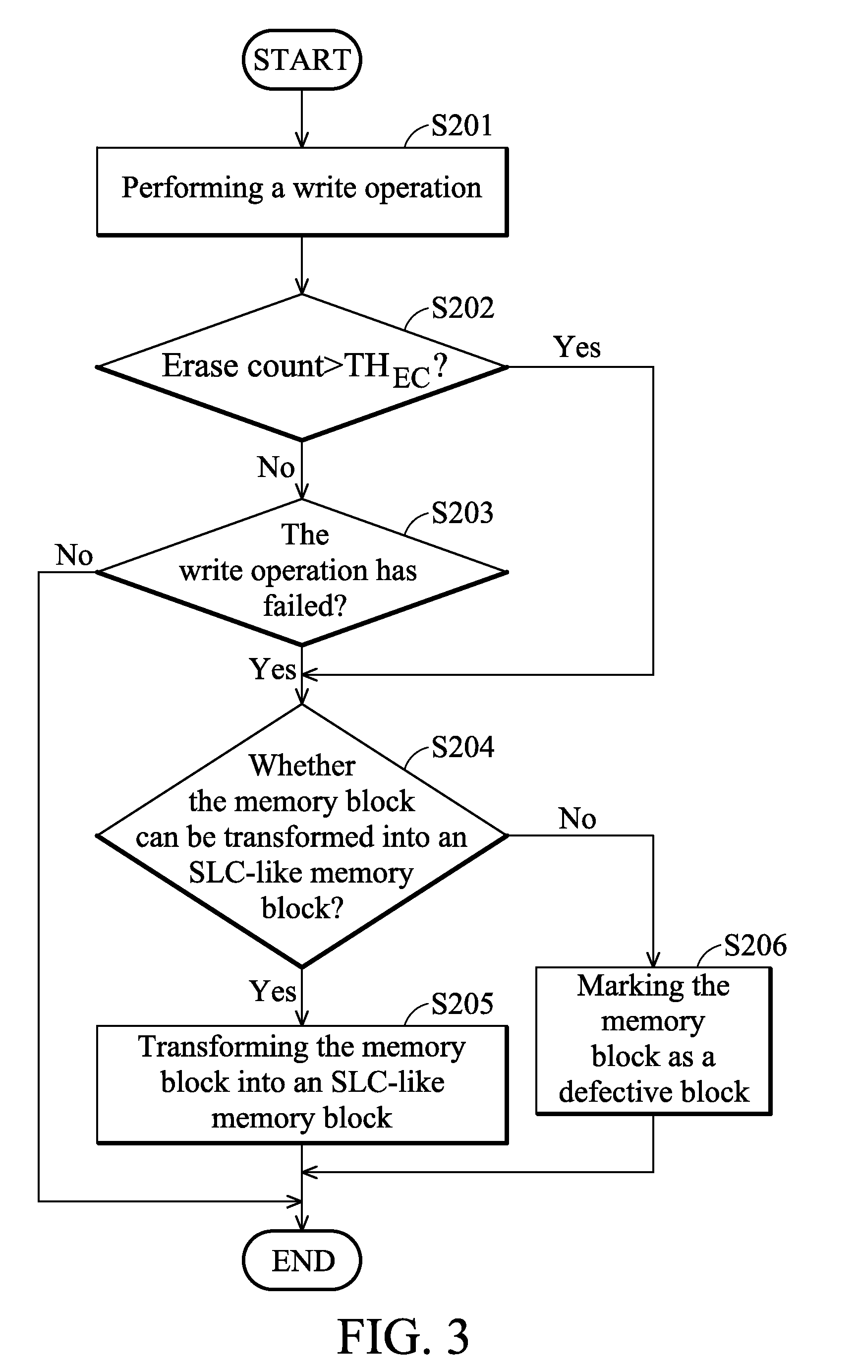
[0024]FIG. 1 shows a solid state disk (SSD) drive configured according to an embodiment of the invention. A solid state disk drive 100 comprises a host interface 101, a controller 102, a buffer 103 and a memory device 104. The host interface 101, serves as an interface between the solid state disk drive 100 and a host (not shown). In general, a host is defined as a system or subsystem that stores information in the solid state disk drive 100. The host interface 101 receives access requests from the host (e.g. read and write operations). The controller 102 is coupled to the host interface 101, receives commands from the host interface 101 and controls the access operati...


PUM


Abstract

A solid state disk drive is provided. The solid state disk drive includes a multiple level cell (MLC) memory device and a controller. The MLC memory device includes memory blocks each comprising memory cells capable of storing more than a single bit of data per cell. The controller transforms at least one memory block into a single level cell (SLC)-like memory block, and accesses the memory block in an SLC manner.

Description

CROSS REFERENCE TO RELATED APPLICATIONS[0001]This application claims the benefit of U.S. Provisional Application No. 61 / 221,569 filed Jun. 30, 2009, and entitled “Apparatus and Operation Method of Flash Memory System”. The entire contents of which are hereby incorporated by reference.BACKGROUND OF THE INVENTION[0002]1. Field of the Invention[0003]The invention relates to a method for managing a memory device, and more particularly to a method for managing a memory device that extends the operating lifespan of the memory device.[0004]2. Description of the Related Art[0005]Flash memory is widely used in electronic products today, especially for portable applications, as a result of its non-volatility and in system re-programmability. The basic structure of a flash memory cell includes a control gate, a drain diffusion region and a source diffusion region disposed on a substrate to form a transistor with a floating gate under the control gate serving as an electron storage device. The ...

Claims


Application Information

Patent Timeline
IPC IPC(8): G06F12/00G11C29/00G06F11/00H03M13/05G06F11/10G06F11/28
CPCG06F2212/7201G11C5/143G11C16/30G06F12/0246
Inventor CHANG, PO-WEIHSIEH, KUN-HUNGTU, LI-CHUNCHANG, TING-CHUNWANG, KUO-HUNG
Owner MEDIATEK INC
Learn More