Power Unit

a power unit and power shaft technology, applied in the direction of hybrid vehicles, couplings, transportation and packaging, etc., can solve the problems of sacrificing the space in the shaft direction of the engine, and achieve the effect of smooth supply and enhanced degree of design freedom

Inactive Publication Date: 2011-01-06
KOMATSU LTD
View PDF5 Cites 54 Cited by
  • Summary
  • Abstract
  • Description
  • Claims
  • Application Information

AI Technical Summary

Benefits of technology

In the invention, the oil passage that communicates the spline joint section engaged with the internal spline of the connection shaft section to the spline joint section engaged with the external spline of the connection shaft section is formed by the hole made in the connection shaft section and the oil passage passing through the gap formed between the end face on one end section side of the connection shaft section and one of the output shaft and the input shaft, which face the end face on one end section side of the connection shaft section.
In the configuration, the lubricant oil that flows into the hole after evenly lubricating the spline joint section engaged with the internal spline of the connection shaft section can flow out toward one end section side of the connection shaft section along the inner circumferential surface of the hole by a centrifugal force of the rotating connection shaft section. The flowing-out lubricant oil is supplied to the spline joint section engaged with the external spline of the connection shaft section through the gap formed between the end face on one end section side of the connection shaft section and one of the output shaft and the input shaft, which face the end face on one end section side of connection shaft section, by the centrifugal force of the rotating connection shaft section.
The lubricant oil that is supplied to the spline joint section engaged with the external spline of the connection shaft section can flow in the axial direction of the connection shaft section after evenly lubricating the spline joint section engaged with the external spline of the connection shaft section.
Thus, in the invention, a large amount of lubricant oil can smoothly be supplied to the two spl

Problems solved by technology

When the damper is provided in mounting the generator motor, unfortunatel

Method used


Image

  • Power Unit
  • Power Unit
  • Power Unit

Examples


Embodiment Construction

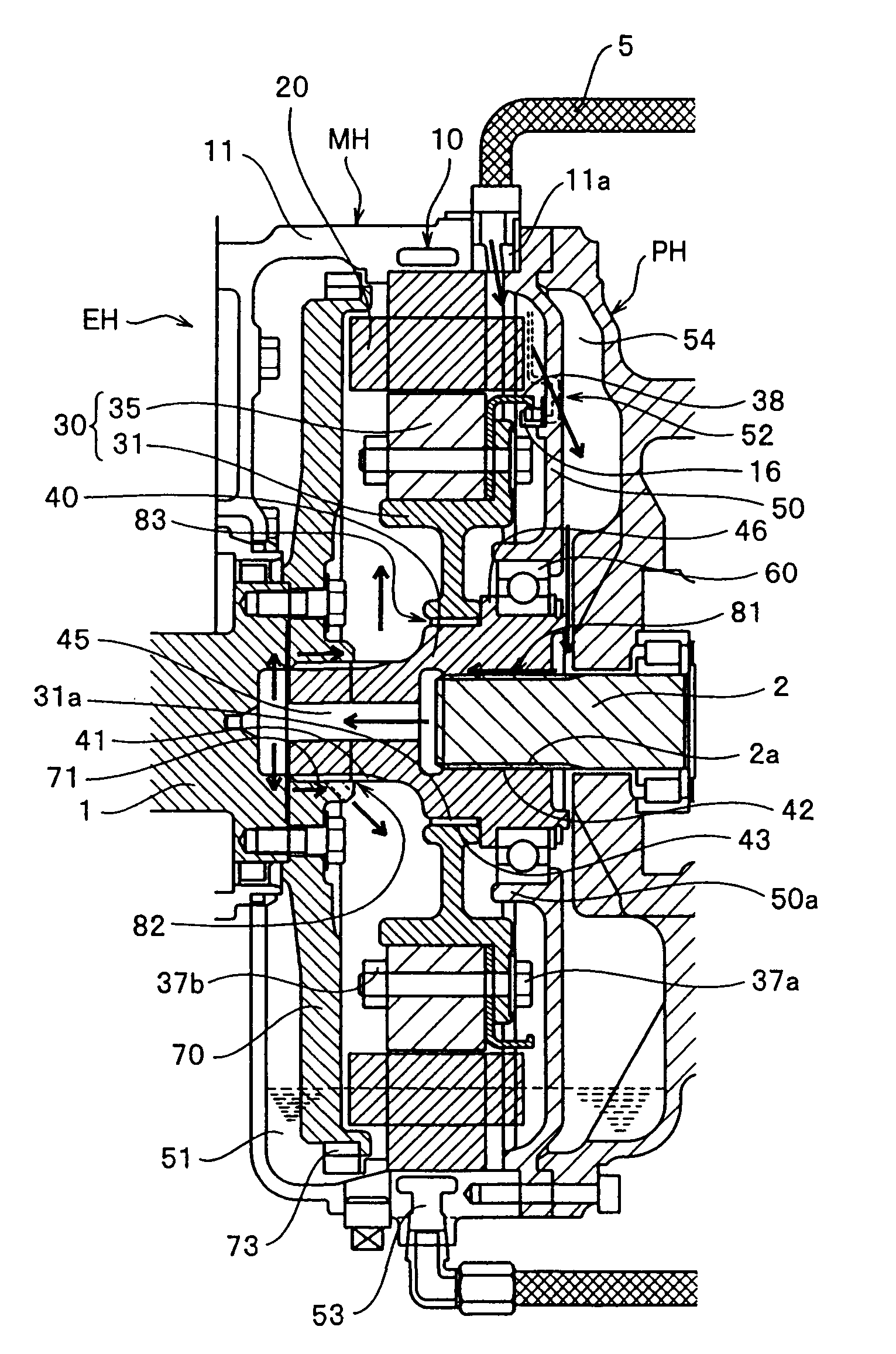
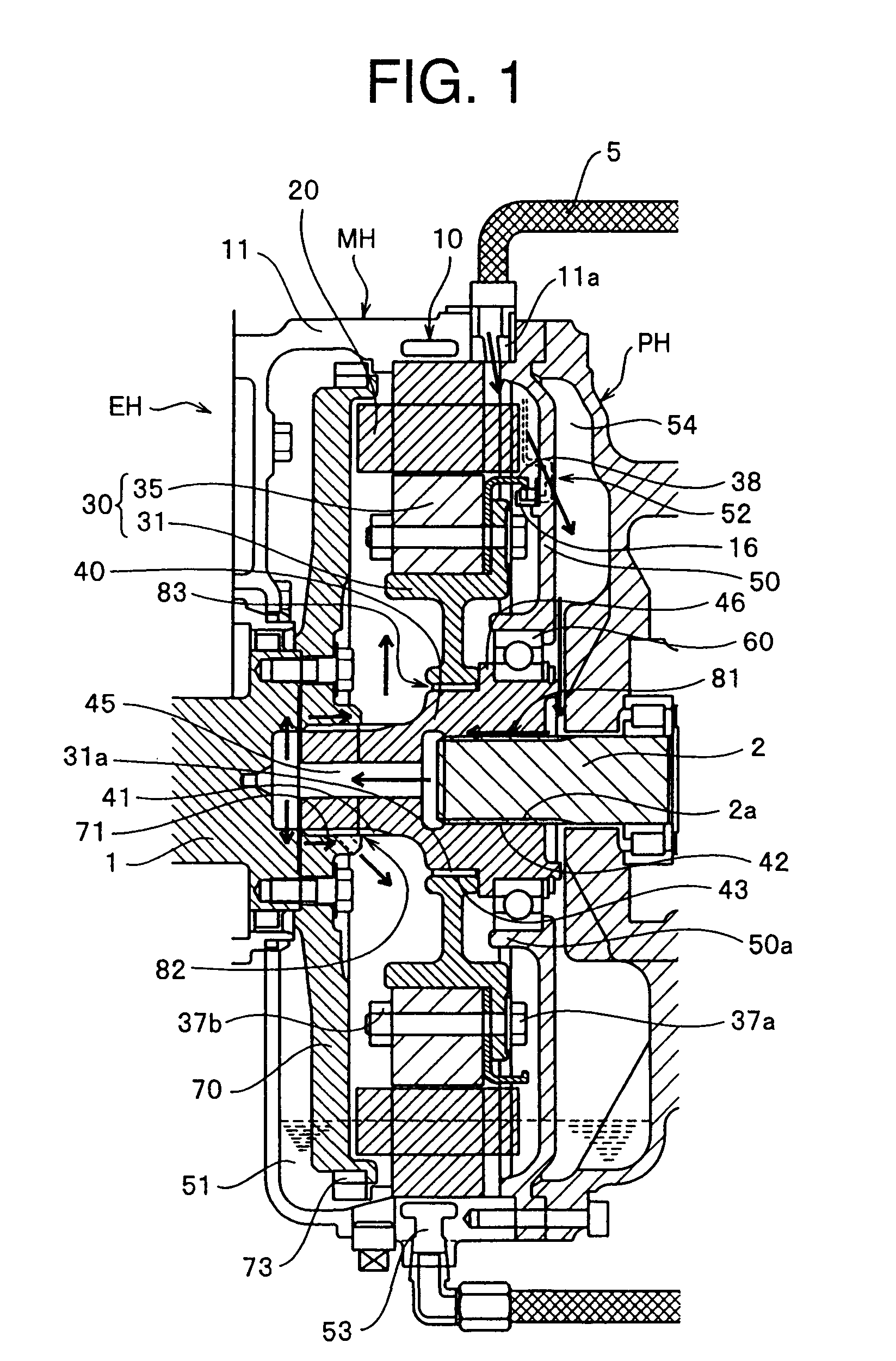
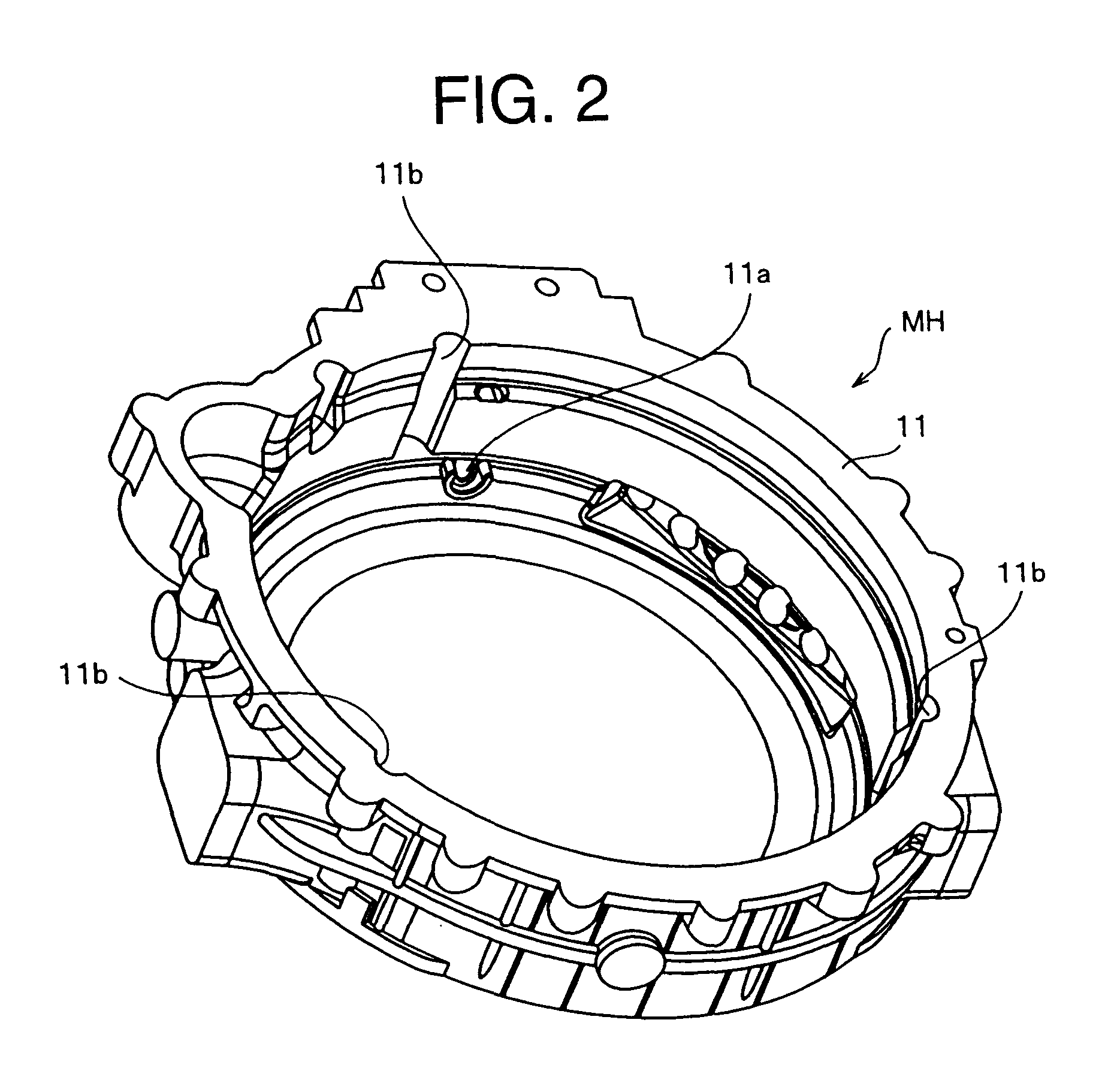
An exemplary embodiment of the present invention will specifically be described with reference to the drawings. FIG. 1 is a longitudinal sectional view passing through an axis line of a generator motor according to an embodiment of the invention. FIGS. 2 to 5 are perspective views of main components of the generator motor. The generator motor of the embodiment is mounted on a hybrid engine applied to a construction machine such as a hydraulic shovel by way of example. However, generator motor of the embodiment can widely be applied to other automobile fields, a general industrial machine field, and large-size engines such as a ship.

As illustrated in FIG. 1, a motor housing MH in which a generator motor 10 is accommodated is fixed between an engine housing EH and a pump housing PH. The engine housing EH and pump housing PH are integrally fixed to each other with the motor housing MH interposed therebetween.

In the engine housing EH, an output shaft 1 directly connected to an engine (n...


PUM


Abstract

An output shaft and an input shaft are connected with a connection member interposed therebetween, and a motor rotor is provided outside the connection member. Part of oil flowing down from an oil supply opening 11a of a motor housing MH is supplied to a first spline joint section of the input shaft and the connection member through a space and an opening of a bearing flange fixed to the motor housing MH. The oil lubricating the first spline joint section moves along an inner circumferential surface of a hole by a centrifugal force generated by rotation of the connection member, the oil moves in a radial direction along an end face on one end section side of the connection member 40 in one end section of the connection member, and the oil is supplied to a second spline joint section of the output shaft and the connection member.

Description

TECHNICAL FIELDThe present invention relates to a power unit that is mounted on an automobile or a construction machine, particularly to a power unit that includes a generator motor as an auxiliary power source for a hybrid engine.BACKGROUND ARTIn the hybrid engine, a hybrid vehicle in which the generator motor is mounted on a flywheel of the engine is already put into practical use in passenger cars and commercial cars such as a bus and a truck. In the hybrid vehicle, a configuration in which the generator motor is mounted in a flywheel housing of the engine is also proposed as PTO (Power Take Off) provided in the engine.Regardless of the hybrid vehicle, desirably components mounted on the vehicle are assembled into compact structures from the viewpoint of restriction of a vehicle installation space. Particularly, the space restriction in a shaft direction of the engine is extremely strict in the restriction of the vehicle installation space.On the other hand, when the generator mo...

Claims


Application Information

Patent Timeline
IPC IPC(8): H02K7/14B60K6/26B60K6/36B60K6/485B60K6/54F16H57/02F16H57/04H02K7/116H02K9/19
CPCB60K6/40B60K6/485B60K6/54F16D1/10Y02T10/6226F16D2300/06H02K5/163H02K7/003H02K9/19F16D2001/103Y02T10/62
Inventor CHIBA, TEIICHIROUSUGIMOTO, YUKIHIKO
Owner KOMATSU LTD
Why Eureka
Try Eureka