
Method for direct connection of mmic amplifiers to balanced antenna aperture

a technology of balanced antenna aperture and amplifier, applied in the field of antenna structure, can solve the problems of not being able to achieve the effect of true antenna characteristics and performance, and achieve the effect of eliminating degraded system performance, reducing ripple associated with coaxial feed, and improving vswr bandwidth

Active Publication Date: 2011-01-06
BAE SYST INFORMATION & ELECTRONICS SYST INTERGRATION INC
View PDF4 Cites 17 Cited by
  • Summary
  • Abstract
  • Description
  • Claims
  • Application Information

AI Technical Summary

Benefits of technology

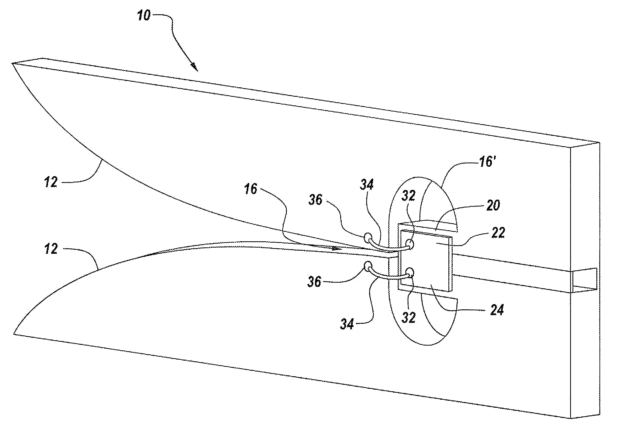
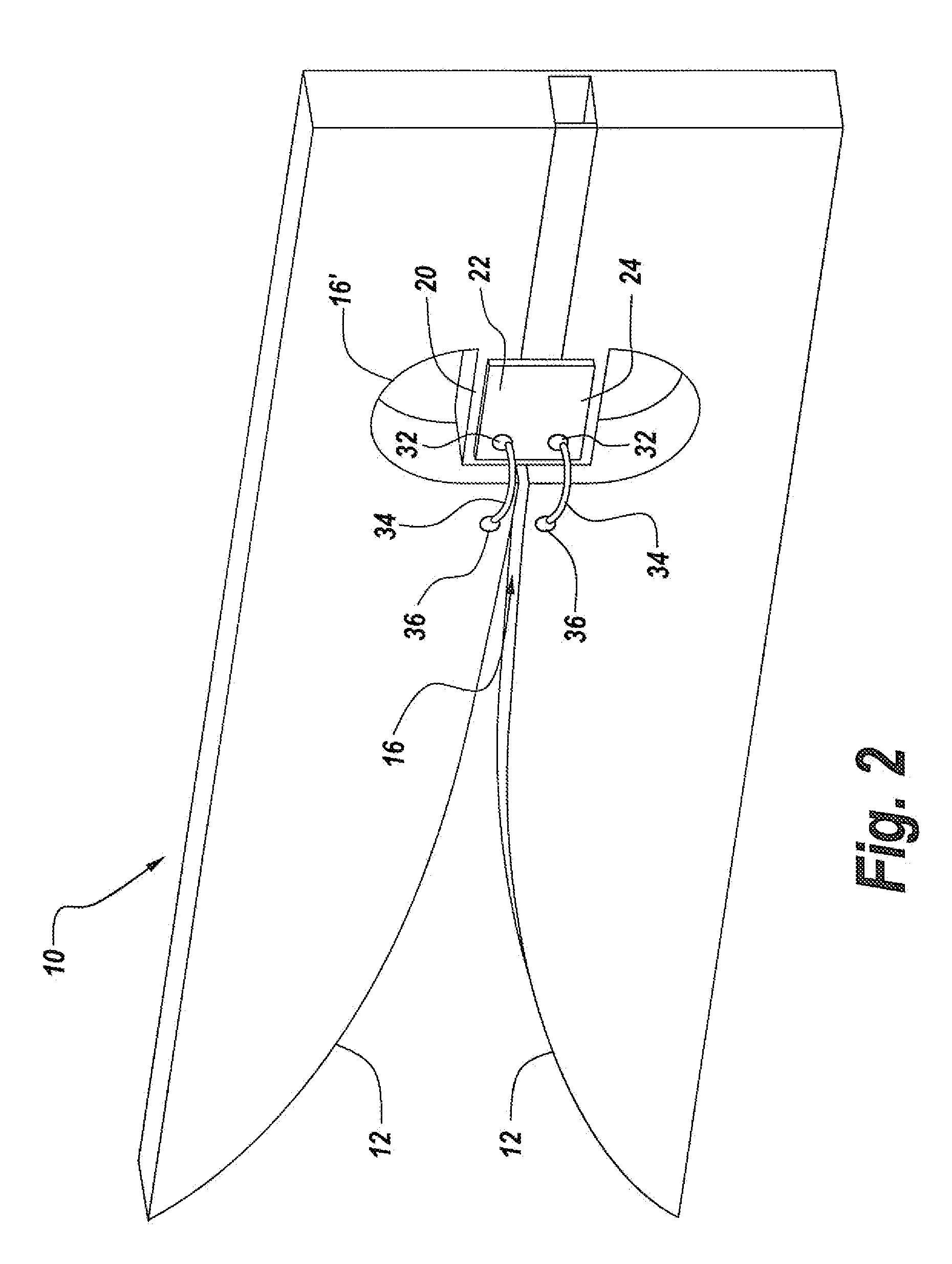
[0013]For a tapered notch, the invention is implemented in one embodiment by expanding the opening behind the feed point called a lagoon. Splitting the lagoon in half and extending the metal of the lagoon in a tab towards the feed point creates a space where miniature electronics can be mounted in such a way that low parasitic connections can be made to the antenna.
[0016]With respect to the Vivaldi notch antennas, it has been found that by enlarging the lagoon and by inserting a metal cantilevered diving board-like tab structure to support the electronics within the lagoon there are no deleterious effects on the properties of the antenna. This permits the placing of an amplifier with a balanced output directly at the feed point of the Vivaldi notch antenna, with a negligible VSWR impact from the split lagoon bridge configuration. Thus, with a direct attachment to a balanced amplifier, one can interface to the Vivaldi notch or tapered notch antenna in a parasitic free environment.
[0018]It will be appreciated that introducing unbalanced electronics at the feed of a bi-cone can result in major asymmetries. However, by providing a symmetric feed to the bi-cone at the bi-cone aperture one improves the VSWR bandwidth. In one embodiment, this feed structure at the bi-cone feed points includes providing balanced lines along ceramic remotes, with the MMIC device below the cone tips.
[0021]In summary, it has been found that it is possible to directly interconnect to the antenna feed points using the balanced input or output of an amplifier, thus to eliminate degraded system performance associated with non-direct multiple interfaces, components and connections which introduce losses and parasitic effects. For receiving, a balanced input amplifier is directly coupled to the antenna feed points, whereas for transmitters an amplifier having a balanced output is directly coupled to the antenna feed points.

Problems solved by technology

While it was felt that altering the antenna aperture would have significant effects on antenna characteristics and performance, this was found not to be true.

Method used


Image

  • Method for direct connection of mmic amplifiers to balanced antenna aperture
  • Method for direct connection of mmic amplifiers to balanced antenna aperture
  • Method for direct connection of mmic amplifiers to balanced antenna aperture

Examples


Embodiment Construction

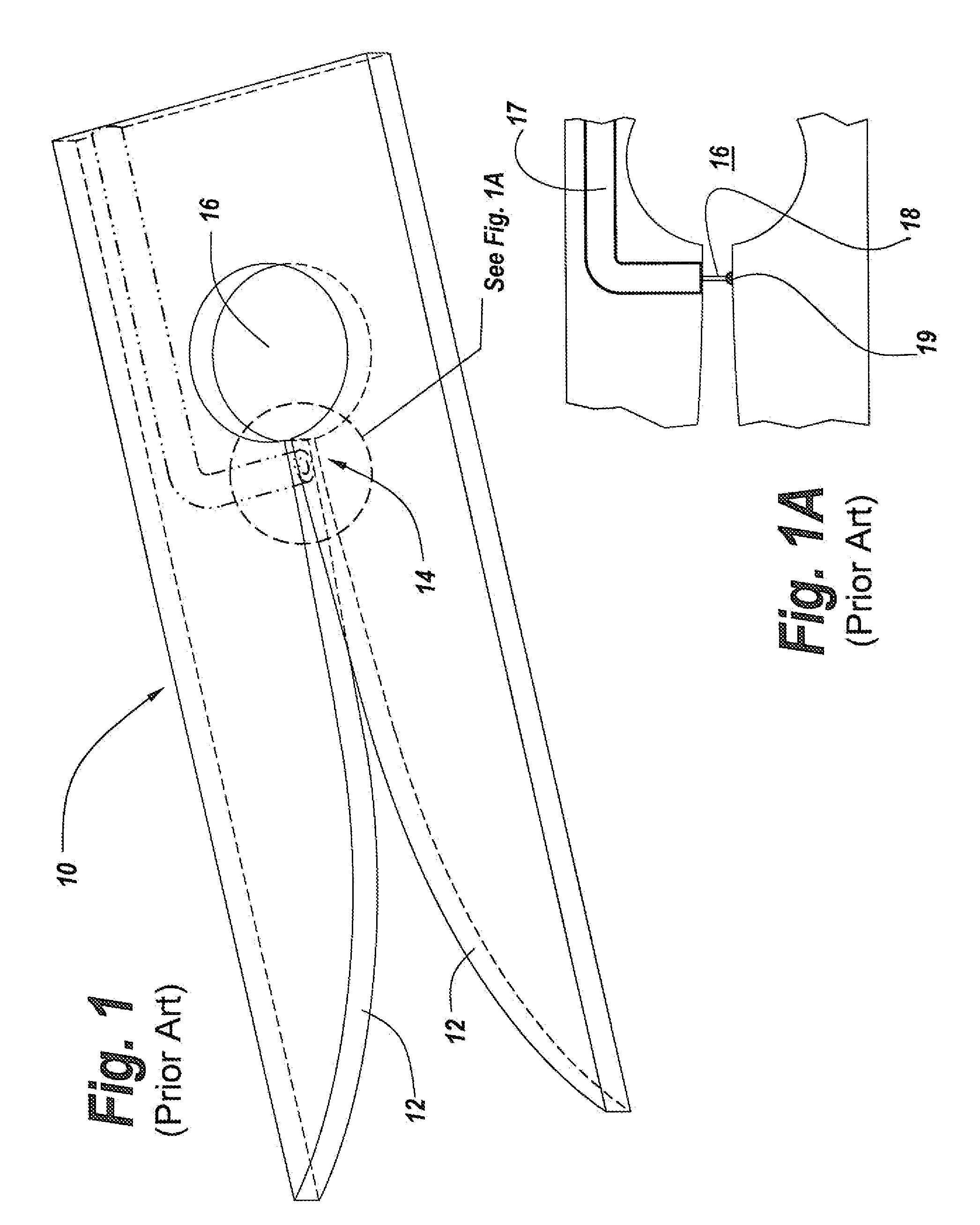
[0037]Referring now to FIG. 1, what is pictured is a traditional Vivaldi notch antenna which is fed by a coaxial line which is by its very nature an unbalanced device. The feed to the Vivaldi notch at the feed points of the antenna present the problem of the impedance mismatch between the balanced feed points of the Vivaldi notch antenna and its unbalanced feed line.

[0038]Here it can be seen that Vivaldi notch antenna has tapered flutes 12 which provide the antenna with an extremely wide bandwidth. These flutes are terminated at a feed point region 14 which is bounded by an open circular region 16 referred to as a lagoon. It is the purpose of this lagoon to act as a broadband tuning stub for the antenna.

[0039]As seen in FIG. 1A, the unbalanced feed utilizes a coaxial cable 17 having a cable conductor 18 that is topped at 19 to the wall of flute 12 to establish the best impedance match possible. However, this is a non-optimal feeding arrangement.

[0040]As mentioned herein, the problem...


PUM

PropertyMeasurementUnit
Sizeaaaaaaaaaa
Electrical conductoraaaaaaaaaa

Abstract

A MMIC amplifier is directly connected to the balanced feed points at the aperture of an antenna to eliminate the distance between electronics coupled to the antenna and the antenna itself, such that interfaces, components and connection lines which introduce losses and parasitic effects that degrade system performance are eliminated due the direct connection. Expanding the aperture of the antenna to accommodate the direct connection of a MMIC amplifier to balanced feed points of an antenna has been found to have no deleterious effects on antenna performance. Moreover, when coupling the MMIC amplifier to an unbalanced coaxial line, any associated ripple is minimized due to the direct connection.

Description

FIELD OF THE INVENTION[0001]This invention relates to antenna structures and more particularly to a method and apparatus for eliminating multiple interfaces, components and connection lines which limit and degrade system performance by placing MMIC amplifier chips or other components at the antenna aperture which provide a balanced output for the balanced feed points of the antenna.BACKGROUND OF THE INVENTION[0002]Current design methodologies for microwave circuit design of MMIC amplifiers generally include the development of a matching network between the complex impedance of the active devices or transistors and a nominal 50 ohm connection impedance. Likewise, antennas are designed to provide a match between the 377 ohm impedance of free space and 50 ohms.[0003]Often these antennas require a transformation between balanced and unbalanced lines or between coaxial and micro-strip transmission lines. Also, note that an antenna element and an amplifier may have a long length transmiss...

Claims


Application Information

Patent Timeline
IPC IPC(8): H01Q1/50
CPCH01Q13/08H01Q13/10H01Q23/00H01L2224/48091H01L2223/6683Y10T29/49018H01L23/66H01L2223/6677H01Q13/04H01L2924/00014
Inventor MEHARRY, DAVID E.CHARETTE, DAVID P.
Owner BAE SYST INFORMATION & ELECTRONICS SYST INTERGRATION INC
Learn More