
Ka wave band flat plate gap array antenna monopulse feed network

A feeding network and monopulse technology, applied to antennas, electrical components, etc., can solve problems such as processing, assembly errors, cumbersome installation and debugging, and affect product performance, and achieve high processing accuracy, convenient antenna sub-array arrangement, and stable performance reliable effect

Inactive Publication Date: 2012-04-25
中国兵器工业第二〇六研究所
View PDF1 Cites 16 Cited by
  • Summary
  • Abstract
  • Description
  • Claims
  • Application Information

AI Technical Summary

Problems solved by technology

[0004] Traditional monopulse networks mostly use waveguide structures, monopulse networks and antennas are independent of each other, the structure is scattered, installation and debugging are cumbersome, especially in the millimeter wave band, waveguide selection, processing, and assembly will introduce large errors, seriously affecting product performance

Method used


Image

  • Ka wave band flat plate gap array antenna monopulse feed network
  • Ka wave band flat plate gap array antenna monopulse feed network
  • Ka wave band flat plate gap array antenna monopulse feed network

Examples


Embodiment Construction

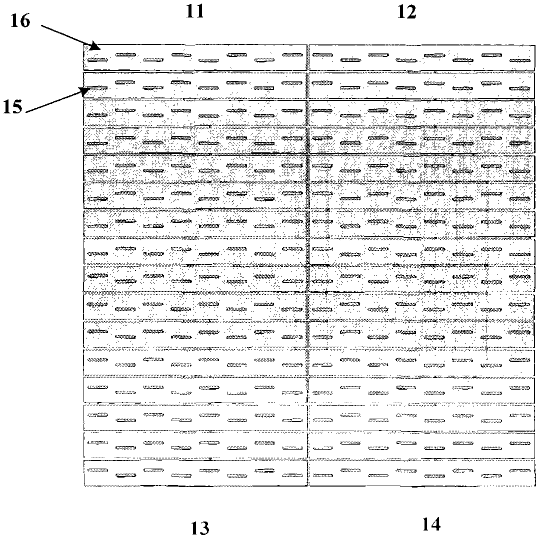
[0021] This embodiment is a Ka-band flat slot array antenna and its monopulse feed network. Reference figure 1 In order to realize the single pulse function, the entire antenna radiation slot feeding layer 1 is divided into 4 quadrants 11, 12, 13 and 14, each quadrant can be further divided into several sub-arrays. In this embodiment, in order to simplify the problem, highlight the key points , Only one sub-array is reserved for each quadrant. The radiation unit of the antenna is a wide-side longitudinal slot 15 of the waveguide, which is arranged on the radiation slot feeder waveguide 16 at equal intervals according to the 1 / 2 waveguide wavelength.

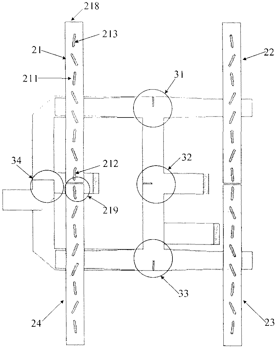
[0022] Reference figure 2 , Ka-band flat slot array antenna monopulse feed network is structurally composed of four layers of waveguide cavities, the top is the radiation slot feed layer 1, followed by the power distribution layer 2, the bottom two layers together form a single pulse Network 3, 4.

[0023] Reference image 3 , The ...


PUM


Abstract

The invention discloses a Ka wave band flat plate gap array antenna monopulse feed network. The feed network is composed of parts such as a radiation gap feed layer, a power distribution network, a monopulse network and the like, wherein the power distribution network adopts a feed waveguide broadside opening inclined joint form, and is used for carrying out coupling feed on the radiation gap feed layer and controlling the feed power through adjusting a feed waveguide centre gap tilt angle; the monopulse network adopts four flat surface magic Ts to form a sum and difference channel in a bell socket manner, and is used for feeding to the power distribution network through a coupling gap, and each flat surface magic T is provided with an inverted-step-shaped metallic membrane, which is used for carrying out voltage standing wave ratio distribution and improving standing wave band width and amplitude-phase consistency band width of each magic T; and coupling folded wave guide is adopted, thus the array radiation gaps are arranged at the same interval, the distance between the last feed inclined joint and the short-circuit end is 1 / 2 waveguide wavelength, and the problem of mutual interference among feed waveguides is solved.

Description

[0001] The invention relates to a millimeter wave microwave device, in particular to a Ka-band flat slot array antenna monopulse feed network, which is used to realize the sum and difference network function of the millimeter wave antenna. technical background [0002] The wavelength of millimeter wave is between infrared wave and microwave, and it has the advantages of both. Compared with infrared wave, millimeter wave is more suitable for complex battlefield environment and harsh weather conditions; compared with microwave, millimeter wave has higher accuracy in detecting targets . [0003] The concept of a monopulse antenna is derived from the self-interferometer, which is developed on the basis of the conical scanning and sequential beam switching system. It can obtain the target's azimuth, elevation angle and distance information within a single radar pulse period. [0004] Traditional monopulse networks mostly use a waveguide structure. The monopulse network and the antenna are...

Claims


Application Information

Patent Timeline
Patent Type & Authority Applications(China)
IPC IPC(8): H01Q25/02
Inventor 李绪平赵交成李斌张胜华
Owner 中国兵器工业第二〇六研究所
Learn More