Imaging apparatus and imaging control method

a technology of imaging control and imaging apparatus, which is applied in the direction of exposure control, instruments, television systems, etc., can solve the problems of inability to control the exposure timing of flashlights of cameras possessed by another person, uneven exposure on the screen, etc., and achieve the effect of accurate detection and reduction of image distortion of moving objects

Inactive Publication Date: 2011-01-06
FUJIFILM CORP
View PDF5 Cites 43 Cited by
  • Summary
  • Abstract
  • Description
  • Claims
  • Application Information

AI Technical Summary

Benefits of technology

[0013]However, the inventions described in Japanese Patent Application Laid-Open Nos. 2006-64974 and 2008-252195 are techniques for reducing the exposure unevenness when a flash device arranged in an imaging apparatus emits a flash. Although emission timing of the flash device arranged on the imaging apparatus can be controlled, the emission timing of flashlight of a camera possessed by another person cannot be controlled.

Problems solved by technology

Although emission timing of the flash device arranged on the imaging apparatus can be controlled, the emission timing of flashlight of a camera possessed by another person cannot be controlled.
Therefore, in a scene such as a wedding ceremony or a press conference, in which a large number of cameras emit flashes at the same time, exposure unevenness occurs in the screen due to flashlight emitted by a camera possessed by another person when an image is taken by the imaging apparatus of the rolling shutter system.
However, the inventions described in Japanese Patent Application Laid-Open Nos. 2006-64974, 2008-252195, 2007-6097, and 2007-49363 cannot solve the problem.

Method used


Image

  • Imaging apparatus and imaging control method
  • Imaging apparatus and imaging control method
  • Imaging apparatus and imaging control method

Examples


first embodiment (

Detection of Exposure Unevenness)

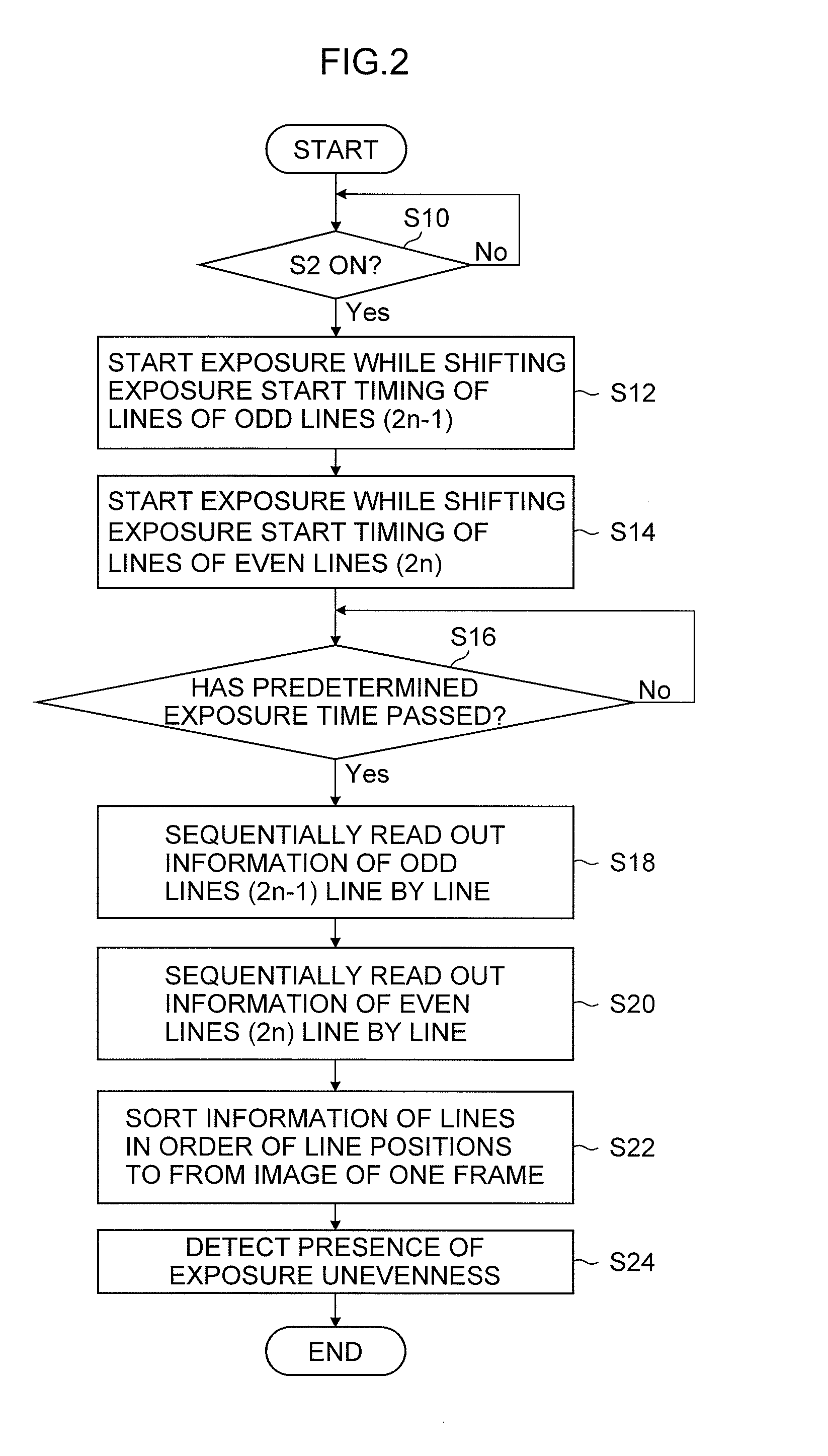
[0097]FIG. 2 is a flow chart showing the first embodiment of the imaging control method according to the present invention and mainly shows a procedure from the start of imaging of a main image to the detection of exposure unevenness.

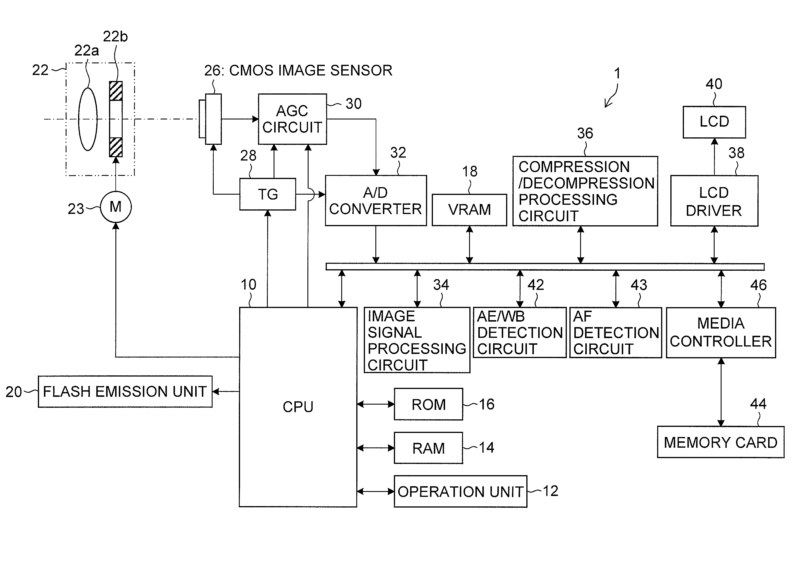
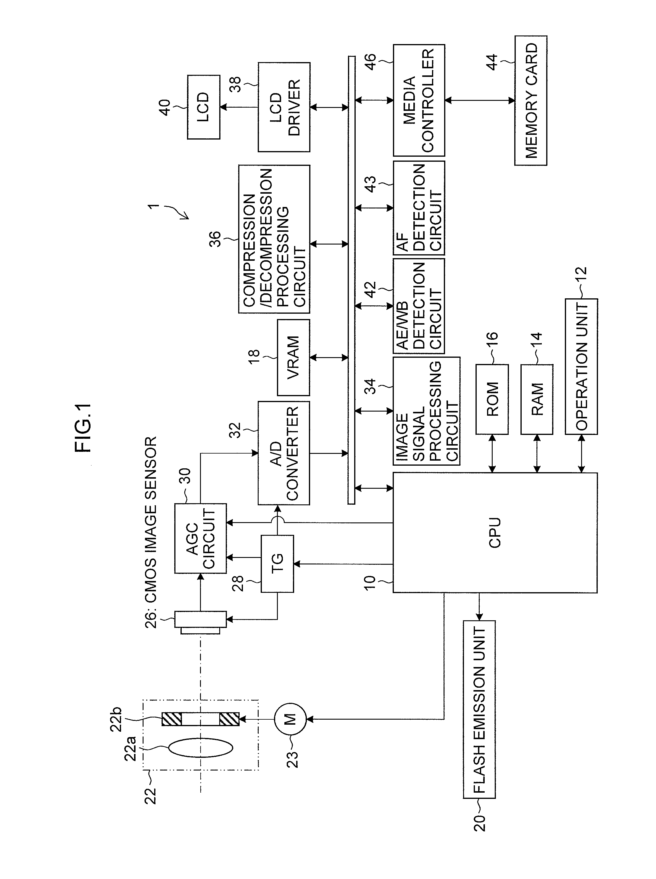
[0098]When the shutter release button is full-pressed (S2 ON), and imaging for recording is instructed to the CPU 10, the CPU 10 controls the aperture device 22b and an electronic shutter, controls the exposure for main imaging, and performs rolling reading of image signals from the CMOS image sensor 26 (steps S10 to S20).

[0099]As shown in FIGS. 3A and 3B, in the exposure control for main imaging, the exposure is started while shifting the exposure start timing by sequentially resetting the odd lines (2n-1) (n=1, 2, 3, . . . ) among all lines of the CMOS image sensor 26 (step S12), and then the exposure is started while shifting the exposure start timing by sequentially resetting the even lines (2n) (n=1, 2, 3, . . . ) (...

second embodiment (

Warning of Exposure Unevenness)

[0123]If it is determined in the process of step S24 that there is exposure unevenness in the main image, the CPU 10 issues a warning of exposure unevenness.

[0124]For the warning of exposure unevenness, for example, a photographed image is displayed on the LCD 40 on the back face of the digital camera 1, and a message, such as “Exposure Unevenness!”, is displayed on the screen of the LCD 40.

[0125]When the warning of exposure unevenness is issued, the photographer checks on the screen of the LCD 40 whether the exposure unevenness has actually occurred. If the detection of the exposure unevenness is a false detection, recording is instructed if the exposure unevenness can be permitted, and a cancel instruction for canceling the recording process of image is issued if the exposure unevenness cannot be permitted. The recording instruction can be issued by pressing the menu / OK key of the operation unit 12, and the cancel instruction can be issued by pressin...

third embodiment (

Correction of Exposure Unevenness)

[0129]FIG. 10 is a flow chart showing a third embodiment of the imaging control method according to the present invention. FIG. 10 particularly illustrates a method of removing exposure unevenness of a main image when the exposure unevenness is detected from the main image obtained by setting a time difference in the odd / even lines shown in FIGS. 3A and 3B to expose and read the lines.

[0130]The CPU 10 first sets n=1 as an initial value of lines of the main image to be processed (step S40).

[0131]The average luminance of pixels of (2n-1) lines (odd lines) and the average luminance of pixels of 2n lines (even lines) are calculated (step S42), and the difference between the average luminances is calculated (step S44).

[0132]The difference value calculated in step S44 is subtracted from the pixels of high-luminance lines among the odd / even lines (step S46). In this way, the luminance is corrected in the pixels of the bright lines with high luminance cause...


PUM


Abstract

According to the present invention, the imaging apparatus of the rolling shutter system first exposes / reads odd lines of an imaging sensor and then exposes / reads even lines. An image of one line is formed by sorting information of the lines, which is obtained by reading the information of the odd lines first and reading the information of the even lines later, in order of line positions. As a result, exposure start timing of adjacent odd / even lines is significantly shifted, and the exposure unevenness has a periodic stripe pattern when the exposure unevenness caused by flash emission of another person, etc. occurs on an image of one frame. Therefore, accurate detection of exposure unevenness caused by flash emission of another person in an imaging apparatus of a rolling shutter system can be achieved.

Description

BACKGROUND OF THE INVENTION[0001]1. Field of the Invention[0002]The present invention relates to an imaging apparatus and an imaging control method, and particularly, to a technique applied to an imaging apparatus of a rolling shutter system.[0003]2. Description of the Related Art[0004]An imaging apparatus has been proposed in which flash emission and exposure timing are matched to prevent in-plane exposure unevenness in a camera with focal plane shutter (Japanese Patent Application Laid-Open No. 2006-64974).[0005]It is known that a reading system in an image apparatus using a CMOS image sensor is a rolling shutter system, in which sequential resetting is performed from the top, and sequential reading is performed.[0006]The rolling shutter system is characterized in that there is a time difference in the exposure timing of the lines as shown in FIG. 26. Therefore, if intense light with short emission period, such as a flash, enters during an exposure period of part of the lines as s...

Claims


Application Information

Patent Timeline
Patent Type & Authority Applications(United States)
IPC IPC(8): H04N5/335
CPCH04N5/3532H04N5/2354H04N23/74H04N25/531
Inventor MATSUURA, TAKAYUKISENBA, TAKEHIKO
Owner FUJIFILM CORP
Why Eureka
Try Eureka