Image synthesizer and image synthesizing method
- Summary
- Abstract
- Description
- Claims
- Application Information
AI Technical Summary
Benefits of technology
Problems solved by technology
Method used
Image
Examples
first embodiment
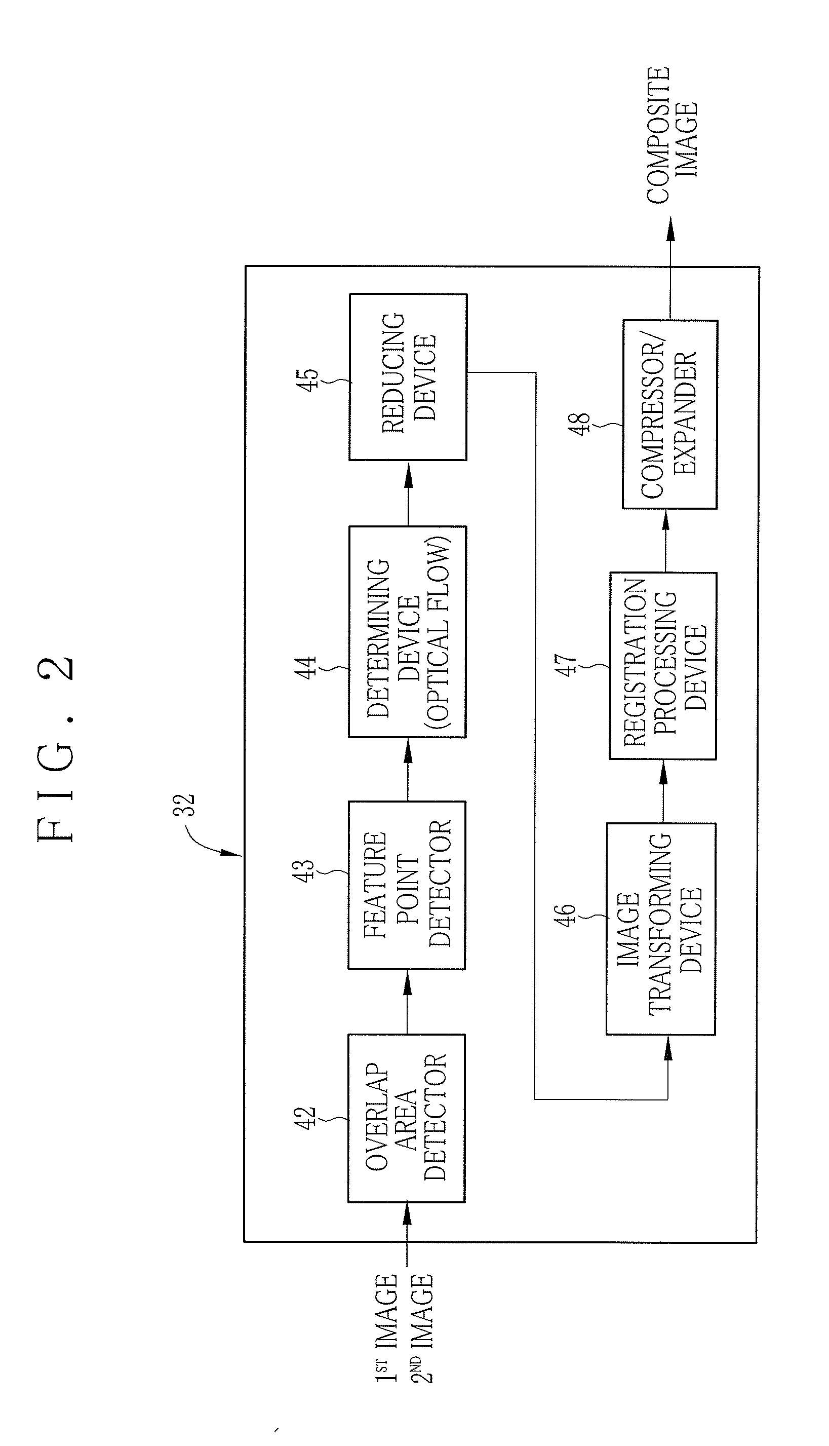
[0089]A second preferred embodiment of the reduction by cancellation is described now. Element similar to those of the above embodiment are designated with identical reference numerals. Although the feature points 65c are reduced randomly in the first embodiment, a problem may arise in insufficient uniformity of the feature points 65c because some of the feature points 65c very near to each other may remain in adjacent areas even after the reduction by cancellation. In view of this, reduction of the feature points 65c is carried out according to an optical flow in each of the partial areas 65e.
[0090]In FIGS. 13A and 14, the reducing device of the second embodiment determines an average optical flow 75 of the feature points 65c for each of the partial areas 65e. In the drawing, the average optical flow 75 is illustrated. Then the reducing device compares an optical flow of the feature points 65c with the average optical flow 75 for each of the partial areas 65e. N of the feature poi...
second embodiment
[0091]A third preferred embodiment of the reduction by cancellation is described now. Element similar to those of the above embodiments are designated with identical reference numerals. Should one of the feature points 65c have an optical flow with a specific difference from the average optical flow in the overlap area 65b in the second embodiment, a problem may arise in an error in the image registration in the vicinity of the feature point 65c with the specific optical flow. In view of this, reduction of the feature points 65c is carried out only to keep at least one of the feature points 65c with a specific optical flow.
[0092]In FIGS. 15A and 16, a reducing device of the third preferred embodiment determines a reference feature point 65f randomly for each of the partial areas 65e. In FIG. 15A, a feature point with the arrow of the optical flow is the reference feature point 65f. The feature points 65c without the arrow are canceled. The reducing device cancels the feature points ...
fourth embodiment
[0094]A fourth preferred embodiment of reduction by cancellation is described now. Elements similar to those of the above embodiments are designated with identical reference numerals. In the above embodiments, the overlap area 65b are segmented into the partial areas 65e to adjust the count of the feature points 65c for each of the partial areas 65e. However, a problem remains in insufficient uniformity of distribution of the feature points 65c due to partial failure of reduction of the feature points 65c within two adjacent areas of the partial areas 65e. In view of this, the fourth embodiment provides further increase in the uniformity of the feature points 65c.
[0095]In FIGS. 17A and 18 for the embodiment, one of the feature points having a shortest distance from an origin of the first image 65 is retrieved as an initial reference feature point. The origin may be a predetermined position in the first image 65, or may be a predetermined position in the overlap area 65b. In the emb...
PUM
 Abstract
Description
Claims
Application Information
 - R&D
- Intellectual Property
- Life Sciences
- Materials
- Tech Scout
- Unparalleled Data Quality
- Higher Quality Content
- 60% Fewer Hallucinations
Browse by: Latest US Patents, China's latest patents, Technical Efficacy Thesaurus, Application Domain, Technology Topic, Popular Technical Reports.
© 2025 PatSnap. All rights reserved.Legal|Privacy policy|Modern Slavery Act Transparency Statement|Sitemap|About US| Contact US: help@patsnap.com


