Apparatus for controlling intake air heating of gas turbine

a technology of gas turbine and intake air, which is applied in the direction of machines/engines, instruments, analogue processes for specific applications, etc., can solve the problem of inability to ensure the stability of the gas turbine, and achieve the effect of increasing the opening rate and increasing the opening ra

Active Publication Date: 2011-01-06
MITSUBISHI POWER LTD
View PDF10 Cites 3 Cited by
  • Summary
  • Abstract
  • Description
  • Claims
  • Application Information

AI Technical Summary

Benefits of technology

[0066]According to the present invention, when steam supplied to the heat exchanger at a start-up time of the gas turbine is switched from auxiliary steam to self-generated steam, the auxiliary steam control valve for controlling a supply amount of auxiliary steam is throttled at a constant rate and, while an opening of the self-generated steam control valve for controlling a supply amount of self-generated steam is being controlled such that a temperature of heated air reaches the target temperature, a rate of the opening is increased.
[0067]That is, at the start-up time, the auxiliary steam control valve is throttled at a constant rate and the self-generated steam control valve is opened while opening control is being performed to the self-generated steam control valve.
[0068]When steam supplied to the heat exchanger at a stopping time of the gas turbine is switched from self-generated steam to auxiliary steam, the self-generated steam control valve for controlling a supply amount of self-generated steam is throttled at a constant rate and, while the opening of the auxiliary steam control valve for controlling a supply amount of auxiliary steam is being controlled such that a temperature of heated air reaches the target temperature, a rate of the opening is increased.
[0069]That is, at the stopping time, the self-generated steam control valve is throttled at a constant rate and the auxiliary steam control valve is opened while opening control is being performed to the auxiliary steam control valve.
[0070]Since such a configuration is adopted in this manner such that, in case that, while one of the self-generated steam control valve and the auxiliary steam control valve is throttled, the other is opened, the one is throttled at a constant rate and the other is opened while an opening of the other is controlled, a temperature of air to be heated can be maintained at a target temperature stably even if steam supplied to the heat exchanger is switched between self-generated steam and auxiliary steam.

Problems solved by technology

The reason why intake air is heated in this manner is because, when dense external air (air) falling within an extremely lower temperature range (for example, −20° C. to −30° C.) is taken by a gas turbine as it is, stable combustion of the gas turbine cannot be assured due to lowering of ignition performance or occurrence of combustion vibrations.
When air with such an extremely low temperature is taken by the gas turbine, there is such a possibility that moisture in the air is frozen at an inlet of the gas turbine, and frozen ice enters the gas turbine to damage a turbine vane or the like.

Method used


Image

  • Apparatus for controlling intake air heating of gas turbine
  • Apparatus for controlling intake air heating of gas turbine
  • Apparatus for controlling intake air heating of gas turbine

Examples


embodiment

[0105]

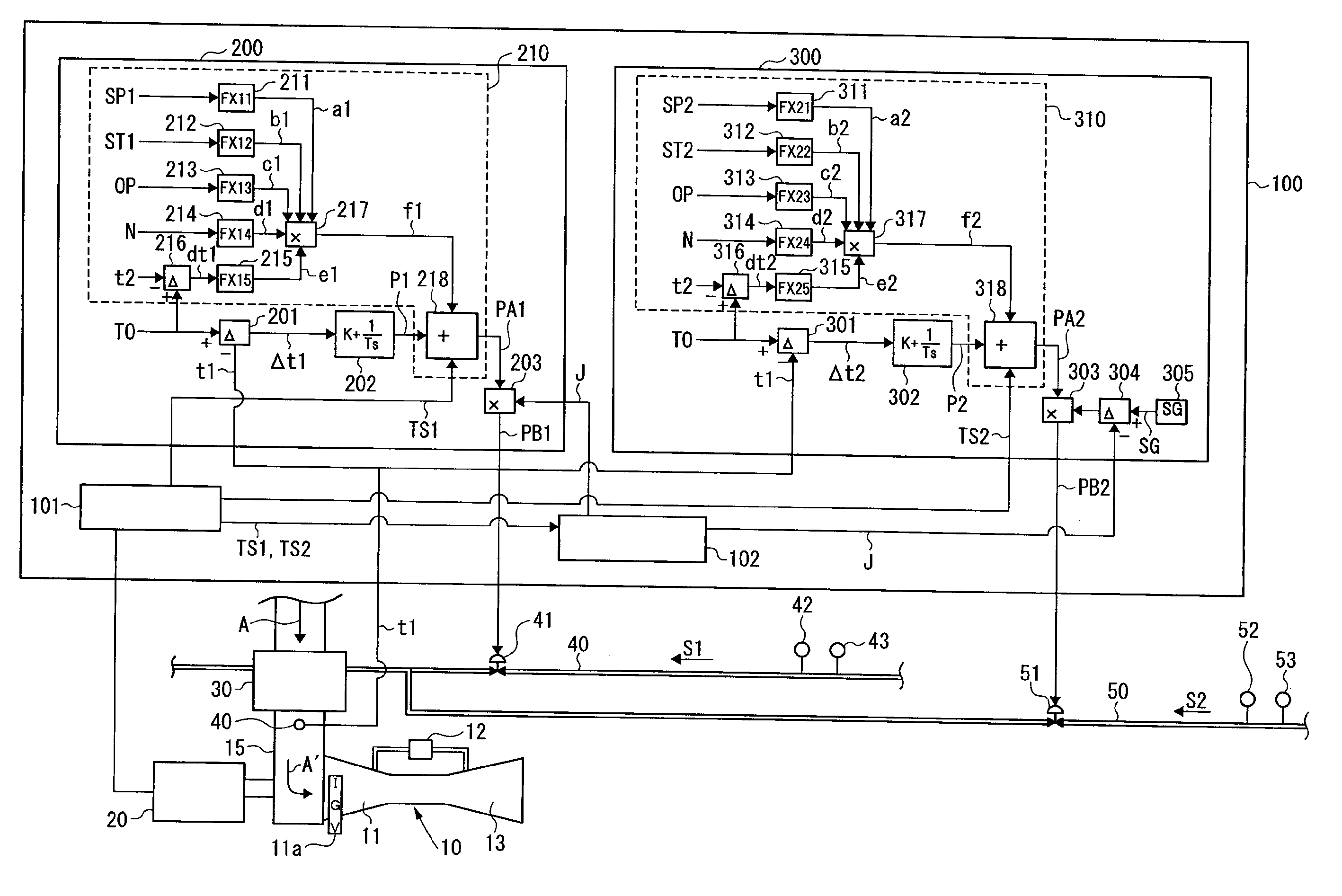
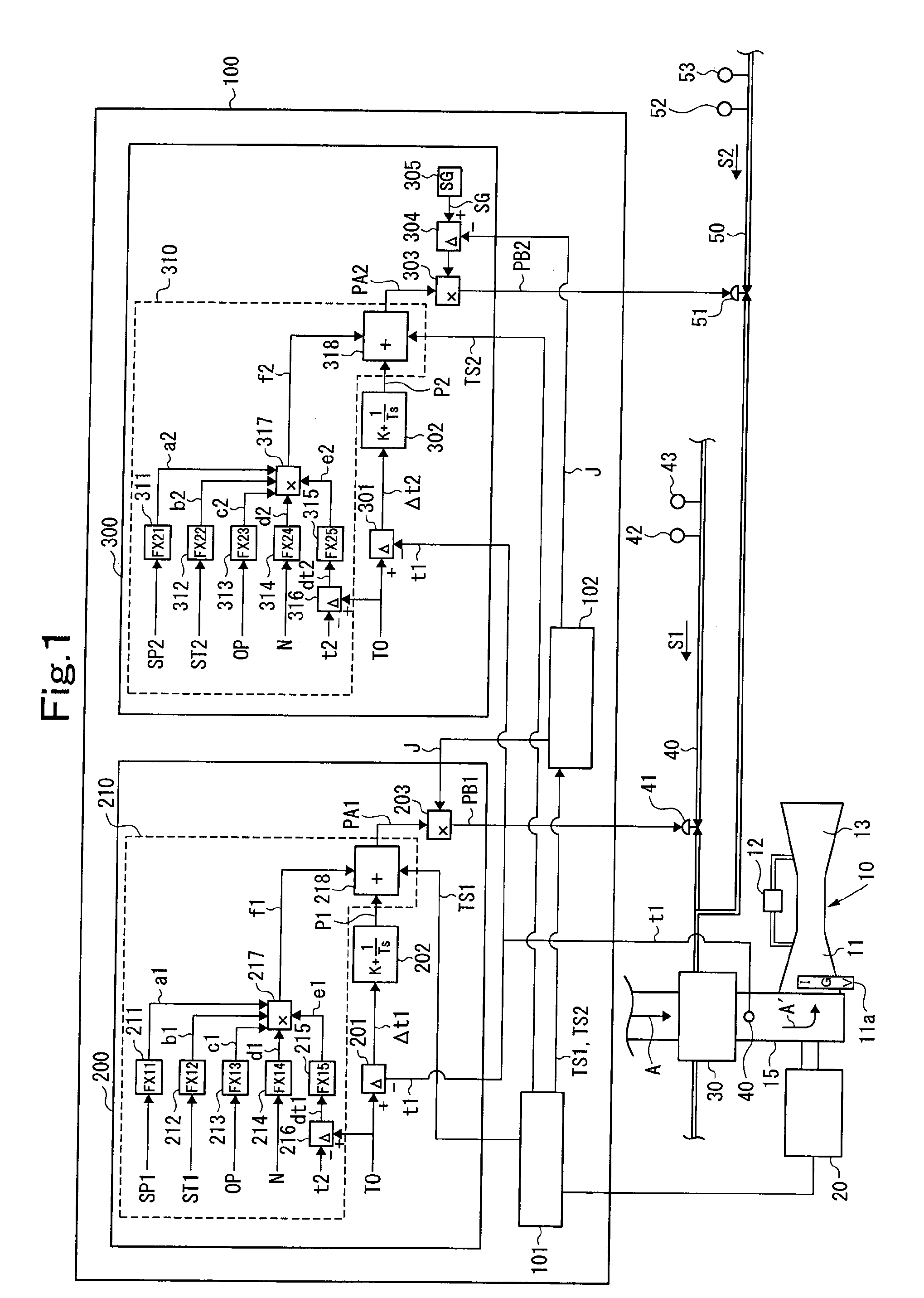
[0106]FIG. 1 shows a gas turbine plant to which an apparatus for controlling intake air heating of a gas turbine according to an embodiment of the present invention has been applied. As shown in FIG. 1, a gas turbine 10 comprises a compressor 11, a combustor 12, and a turbine 13 as main components. Air (atmosphere) “A” taken from the outside is taken by the compressor 11 of the gas turbine 10 via an intake air duct 15.

[0107]An inlet of the compressor 11 is provided with an inlet guide vane (IGV) 11a, and an amount of air taken by the compressor 11 is controlled by an opening of the IGV 11a. Incidentally, the opening of the IGV 11a is controlled according to a load state, an operating state, or the like.

[0108]A generator 20 is coupled to the gas turbine 10 to be rotationally driven by the gas turbine 10, thereby generating electric power.

[0109]A heat exchanger 30 for intake air heating is arranged in the intake air duct 15. The heat exchanger 30 is supplied with self-generated ...


PUM


Abstract

In a heating apparatus for heating the air sucked into a gas turbine by a heat exchanger, the temperature fluctuation of the heated air is suppressed even in the period, for which a steam source to be fed to the heat exchanger is changed. For that suppression, a heat exchanger (30) is fed with both a self-can steam (S1), the feed rate of which is controlled by a self-can steam control valve (41), and the auxiliary-steam (S2), the feed rate of which is controlled by an auxiliary-steam control valve (51). At the starting time, the quantity of the auxiliary-steam (S2) is reduced at a constant rate, and the quantity of the self-can steam (S1) is increased while a feedback control and a feedforward control are being made. At the stopping time, the quantity of the self-can steam (S1) is reduced at a constant rate, and the quantity of the auxiliary-steam (S2) is increased while the feedback control and the feedforward control are being made.

Description

TECHNICAL FIELD[0001]The present invention relates to an apparatus for controlling intake air heating of a gas turbine.[0002]More specifically, the present invention is devised so as to maintain a temperature of intake air constant even if a steam source is changed in an intake air heating apparatus of a gas turbine which heats air taken by the gas turbine by steam.BACKGROUND ART[0003]In a gas turbine installed in a cold area, after air taken from atmosphere is heated, it is taken by the gas turbine.[0004]The reason why intake air is heated in this manner is because, when dense external air (air) falling within an extremely lower temperature range (for example, −20° C. to −30° C.) is taken by a gas turbine as it is, stable combustion of the gas turbine cannot be assured due to lowering of ignition performance or occurrence of combustion vibrations. When air with such an extremely low temperature is taken by the gas turbine, there is such a possibility that moisture in the air is fro...

Claims


Application Information

Patent Timeline
Patent Type & Authority Applications(United States)
IPC IPC(8): F02C9/00
CPCF02C7/047F02C7/057F05D2260/2322F05D2270/303F02C7/08
Inventor TANAKA, SATOSHIHARADA, SHOICHI
Owner MITSUBISHI POWER LTD
Why Eureka
Try Eureka