Particulate matter reduction apparatus for diesel engine

a technology for diesel engines and reducing apparatuses, which is applied in mechanical equipment, machines/engines, transportation and packaging, etc., can solve the problems of reducing the life of filters, affecting the efficiency of filters, so as to reduce the size of filters. , the effect of simple structur

Inactive Publication Date: 2011-01-13
IND ACADEMIC COOPERATION FOUND JEJU NAT UNIVERSTIY
View PDF19 Cites 12 Cited by
  • Summary
  • Abstract
  • Description
  • Claims
  • Application Information

AI Technical Summary

Benefits of technology

[0011]The following description relates to a particulate matter reduction apparatus for a diesel engine which can easily reduce particulate matter with a simple structure while preventing reduction of lifespan of a filter and increasing combustion efficiency with respect to particulate matter.

Problems solved by technology

In use of the DPF, a method of removing the collected particulate matter has arisen as a key issue.
However, although this method does not require a diesel vehicle to be equipped with another device, it does cause users the inconvenience of having to exchange filters periodically.
However, since the above method requires an electric heater or a diesel burner to be additionally installed, it complicates the structure of the filter and increases manufacturing cost.
Moreover, a portion of the filter close to the electric heater or the diesel burner can be overheated, and consequently it may shorten the lifespan of the filter.
However, the use of an additive is disadvantageous in that a specific type of a fuel must be used, for example, mass fraction of sulfur contained in the fuel is should be smaller than a certain value.
Furthermore, the method of applying a catalyst to a filter is not as efficient as the method of adding the additive in fuels in terms of lowering a temperature that is capable of igniting particulate matter, and thus an additional heat source or additive is required.

Method used


Image

  • Particulate matter reduction apparatus for diesel engine
  • Particulate matter reduction apparatus for diesel engine
  • Particulate matter reduction apparatus for diesel engine

Examples


Embodiment Construction

[0027]The following description is provided to assist the reader in gaining a comprehensive understanding of the methods, apparatuses, and / or systems described herein. Accordingly, various changes, modifications, and equivalents of the methods, apparatuses, and / or systems described herein will be suggested to those of ordinary skill in the art. Also, descriptions of well-known functions and constructions may be omitted for increased clarity and conciseness.

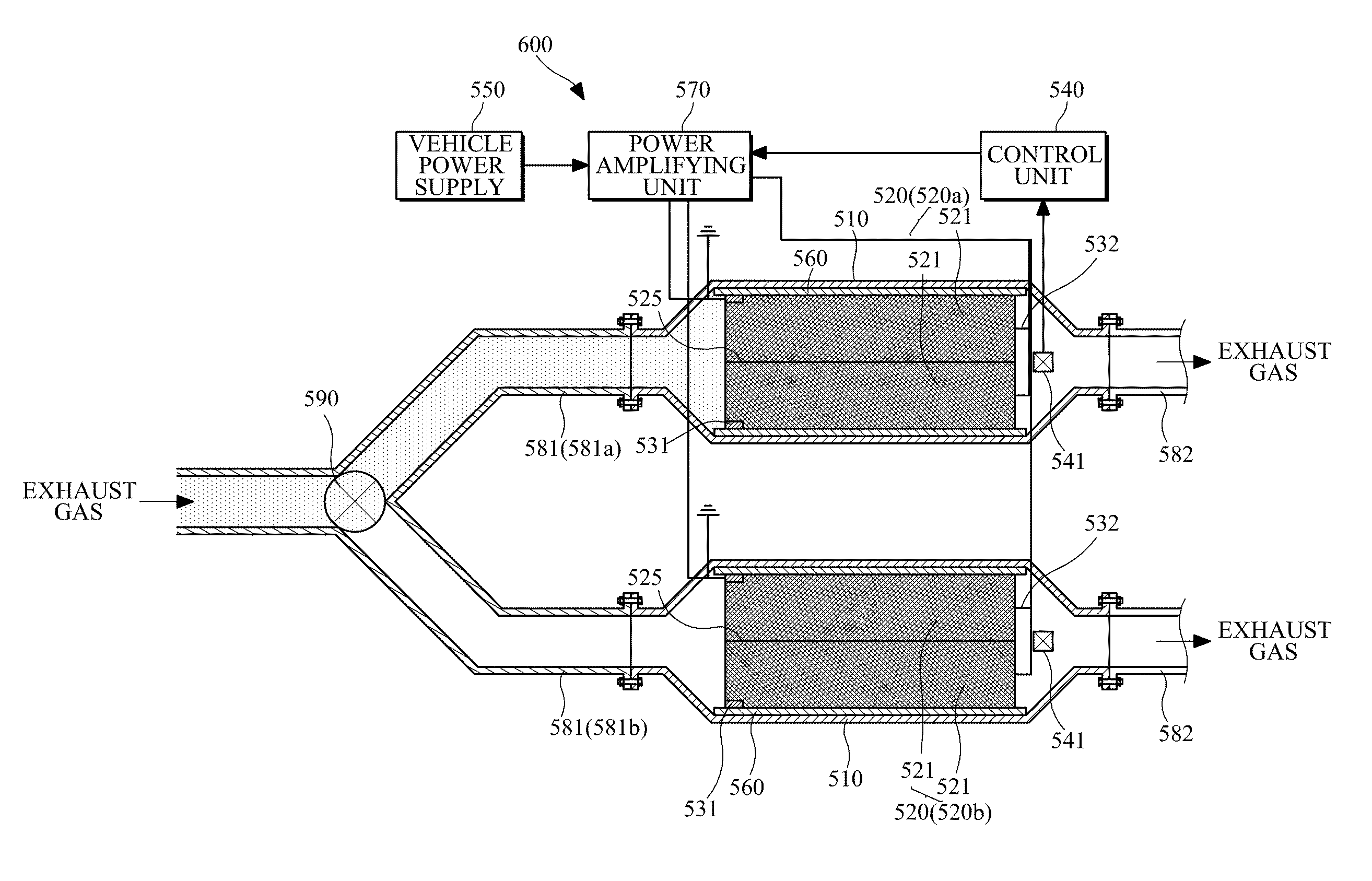
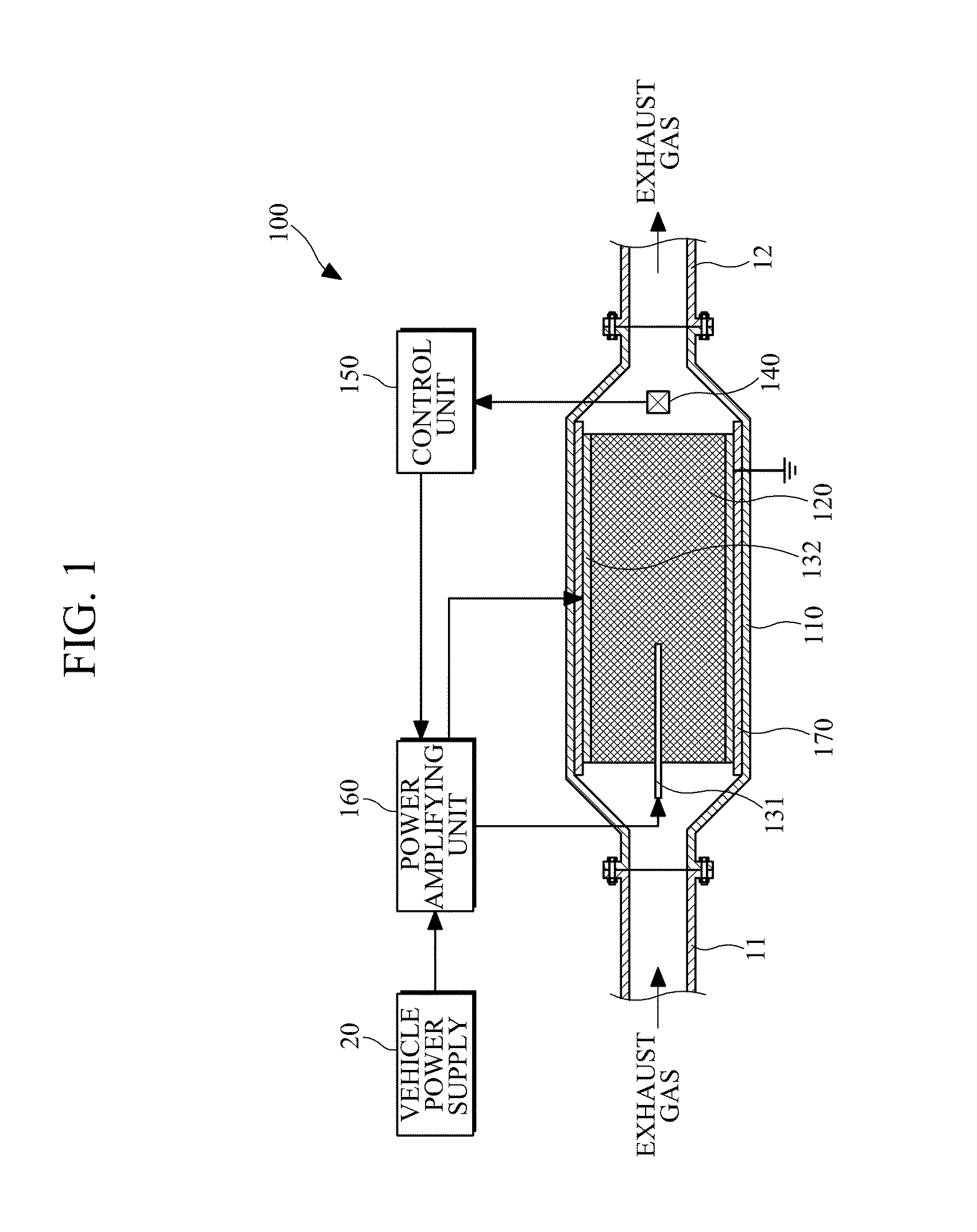
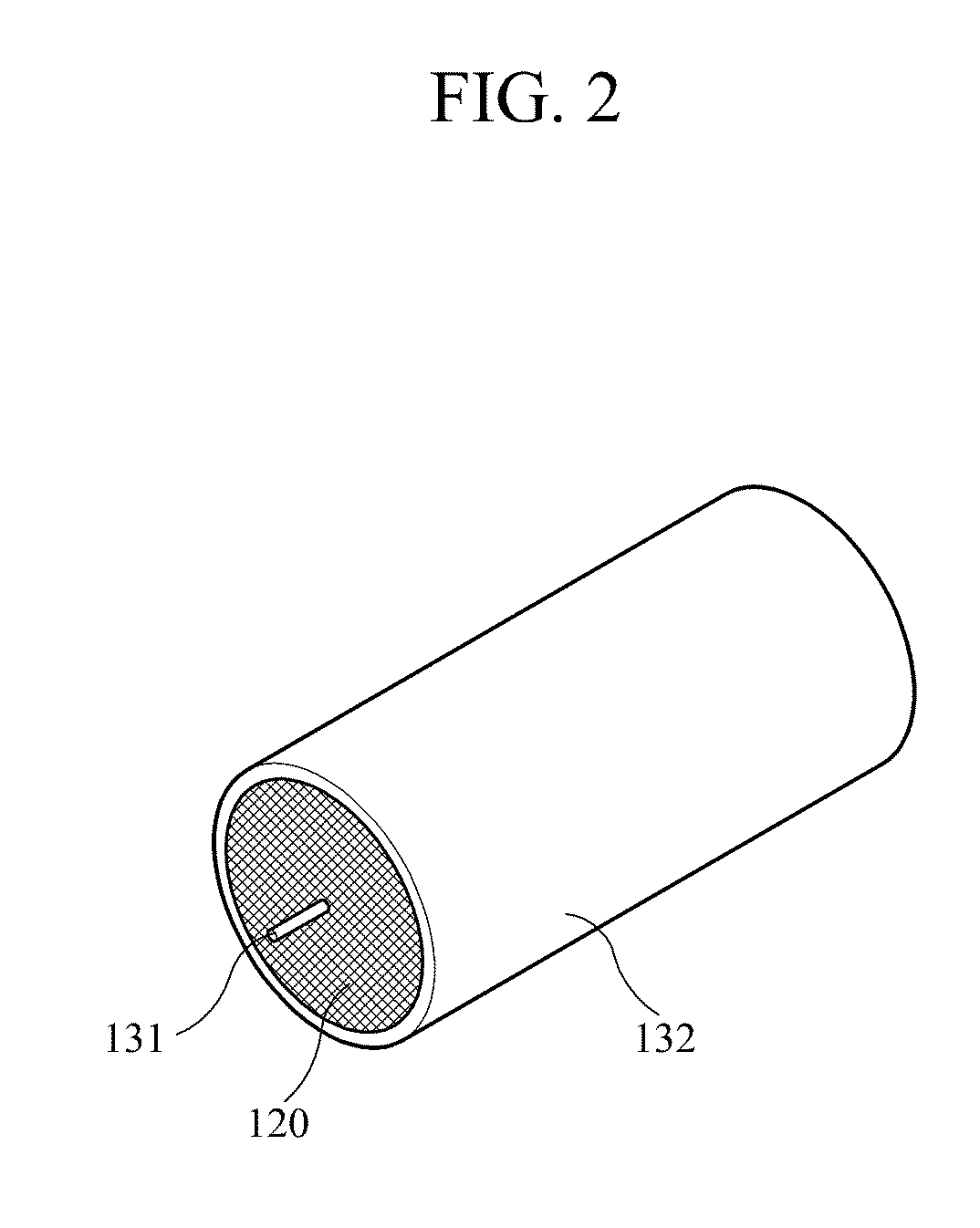
[0028]FIG. 1 illustrates an example of a particulate matter reduction apparatus for a diesel engine. Referring to FIG. 1, the particulate matter reduction apparatus 100 may include a housing 110, a diesel particulate filter (DPF) 120, a plurality of electrodes 131 and 132, and a control unit 150.

[0029]The housing 110 is provided on a flow path along which exhaust gas is discharged from the diesel engine. Accordingly, the exhaust gas discharged from the diesel engine is allowed to flow into the housing 110. The housing 110 may be c...


PUM

PropertyMeasurementUnit
angleaaaaaaaaaa
angleaaaaaaaaaa
thicknessaaaaaaaaaa

Abstract

A particulate matter reduction apparatus for a diesel engine, which can reduce particulate matter in a convenient manner with a relatively simple structure, while preventing the shortening of the lifespan of a filter and improving particulate matter burning efficiency, is provided. The particulate matter reduction apparatus includes a housing configured to be placed on a flow path into which exhaust gas is discharged from the diesel engine, a filter configured to collect particulate matter contained in the exhaust gas that flows in the housing, electrodes configured to transmit electronic signals to the filter, and a control unit configured to control the electric signals provided to the electrodes. The particulate matter reduction apparatus is advantageous in that particulate matter is burnt and removed by directly heating the filter. In addition, the apparatus is more convenient, compared to a system which requires a filter to be separated and cleaned. In addition, the particulate matter reduction apparatus has a more simplified structure, compared to a system that heats a filter using an electric heater or a is diesel burner. Accordingly, the manufacturing cost can be reduced. Furthermore, the particulate matter reduction apparatus is advantageous in that the filter is relatively uniformly heated rather than being partially heated, so that a long lifespan of the filter can be assured.

Description

CROSS-REFERENCE TO RELATED APPLICATION[0001]This application claims the benefit under 35 U.S.C. §119(a) of International Patent Application No. PCT / KR2009 / 000844, filed on Feb. 23, 2009, the entire disclosure of which is incorporated herein by reference for all purposes.BACKGROUND[0002]1. Field[0003]The following description relates to a particulate matter reduction apparatus for a diesel engine, which reduces particulate matters in exhaust gas discharged from a diesel engine.[0004]2. Description of the Related Art[0005]A diesel engine employed in an automobile, a diesel vessel and a diesel locomotive has is advantages of superior fuel economy and powerful output, however it is by its nature bound to discharge a significant amount of particulate matters included in the exhaust gas, unlike a gasoline engine.[0006]Since particulate matters are regarded as a main factor of air pollution, regulations limiting the particulate matters have been tightened. Accordingly, a diesel engine is e...

Claims


Application Information

Patent Timeline
Patent Type & Authority Applications(United States)
IPC IPC(8): F01N3/00F01N9/00F01N3/035
CPCB01D46/0063F01N3/031F01N9/002F01N2560/06F01N3/027F01N13/011F01N3/2853F01N3/035F01N2900/1602Y02T10/47F01N3/0275Y02T10/40B01D46/84
Inventor LEE, HEON-JUPLAKSIN, VADIM YUREVICH
Owner IND ACADEMIC COOPERATION FOUND JEJU NAT UNIVERSTIY
Why Eureka
Try Eureka