Electric Power Plant, and Method for Running Electric Power Plant

a technology for electric power plants and power plants, which is applied in the direction of nuclear power plants, machines/engines, nuclear engineering, etc., can solve the problems of reducing the efficiency of thermal power plants, the amount of electric power consumed by driving compressors is also large, and the need for large compressors, so as to increase the thermal efficiency of the plant and increase the power output

Active Publication Date: 2011-01-13
HITACHI-GE NUCLEAR ENERGY LTD
View PDF4 Cites 14 Cited by
  • Summary
  • Abstract
  • Description
  • Claims
  • Application Information

AI Technical Summary

Benefits of technology

[0015]According to the present invention, it is possible to provide an electric power plant and a method for runni

Problems solved by technology

The inventors then found problems in that the compressor needs to be large and the amount of electric power consumed by driving the compressor is also large in order to supply compressed air to four feed water heaters by the use of one compressor as in the thermal power plant described in Japan

Method used


Image

  • Electric Power Plant, and Method for Running Electric Power Plant
  • Electric Power Plant, and Method for Running Electric Power Plant
  • Electric Power Plant, and Method for Running Electric Power Plant

Examples


first embodiment

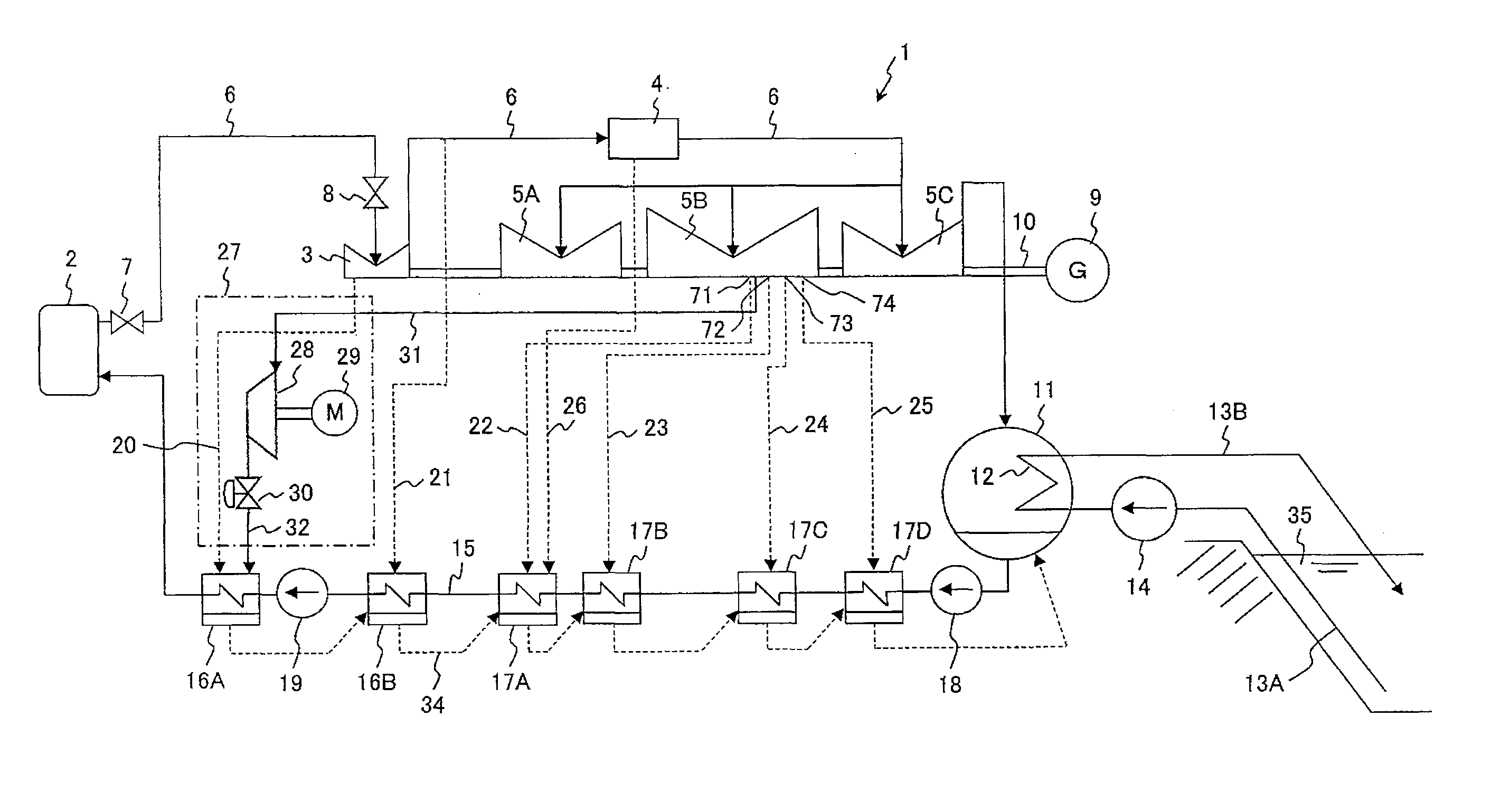
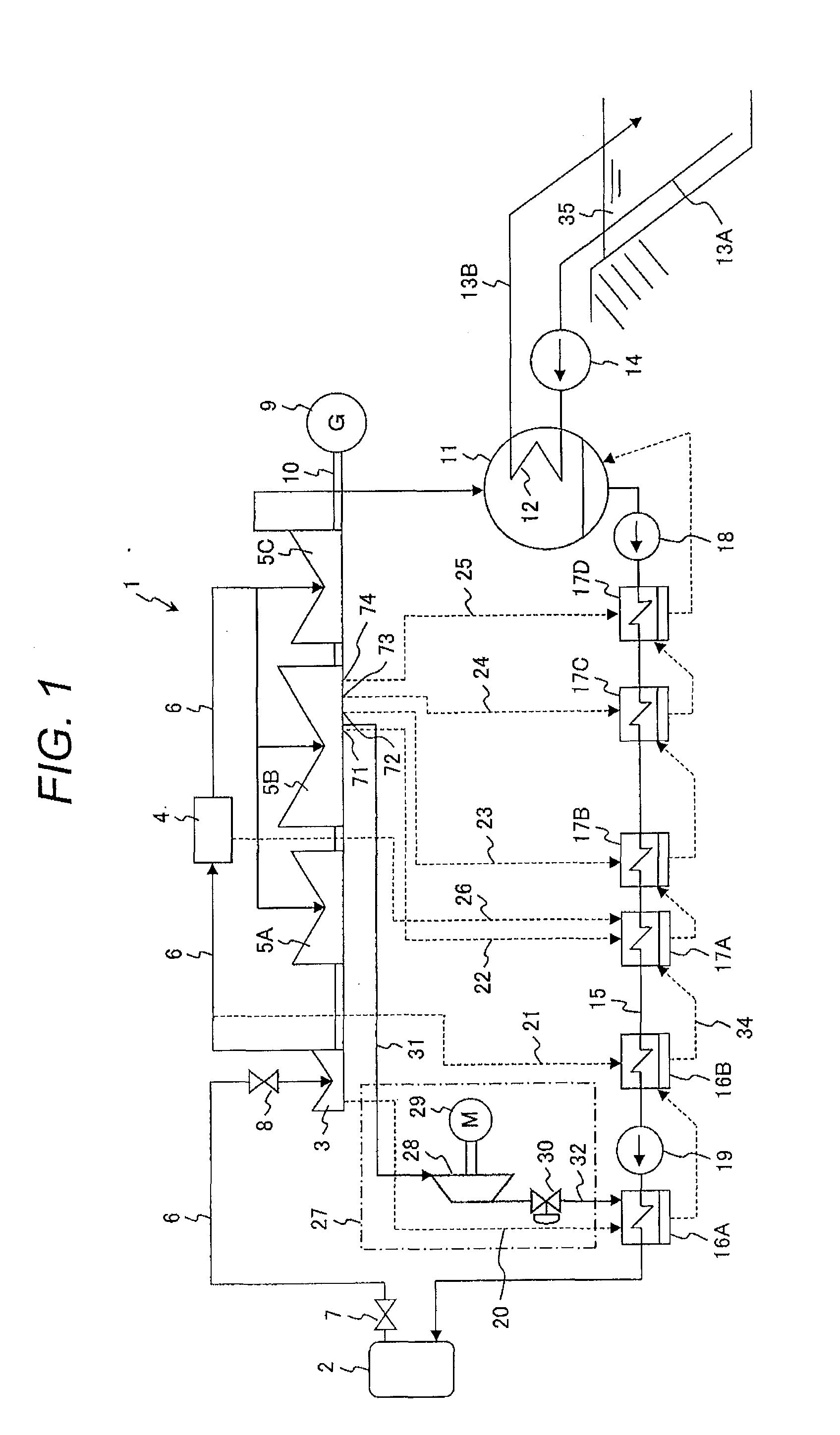
[0097]An electric power plant according to a first embodiment which is a preferred embodiment of the present invention will be described with reference to FIG. 1. The electric power plant in this embodiment is an 1100 MWe BWR-5 type BWR nuclear power plant.

[0098]The BWR nuclear power plant 1 includes: a nuclear reactor 2 working as a steam generating apparatus; a high-pressure turbine (first turbine) 3; low-pressure turbines (second turbines) 5A, 5B and 5C; a main steam pipe 6; a condenser 11; a plurality of feed water heaters; a feed water pipe 15; and a steam compression apparatus 27. Those feed water heaters include: a first high-pressure feed water heater 16A; a second high-pressure feed water heater 16B; a third low-pressure feed water heater (first low-pressure feed water heater) 17A; a fourth low-pressure feed water heater (second low-pressure feed water heater) 17B; a fifth low-pressure feed water heater (third low-pressure feed water heater) 17C; and a sixth low-pressure fe...

second embodiment

[0125]An electric power plant according to a second embodiment which is another embodiment of the present invention will be described with reference to FIG. 9. The electric power plant in this embodiment is also an 1100 MWe BWR-5 type BWR nuclear power plant 1A. The BWR nuclear power plant 1A has a configuration in which the steam compression apparatus 27 of the BWR nuclear power plant 1 in the first embodiment is replaced by a steam compression apparatus 27A. The steam feed pipe 31 is connected to the steam extraction point 72 (second location). The other configuration of the BWR nuclear power plant 1A is the same as the configuration of the BWR nuclear power plant 1.

[0126]In FIG. 9, feed water heaters other than the first high-pressure feed water heater 16A and the fifth low-pressure feed water heater 17C and extraction pipes other than the extraction pipes 20 and 24 are omitted. This is the same as in FIG. 10, FIG. 11, FIG. 15, FIG. 17, FIG. 18, and FIG. 19, to be described later...

third embodiment

[0135]An electric power plant according to a third embodiment which is another embodiment of the present invention will be described with reference to FIG. 10. The electric power plant in this embodiment is also an 1100 MWe BWR-5 type BWR nuclear power plant 1B. The BWR nuclear power plant 1B has a configuration in which the steam compression apparatus 27 of the BWR nuclear power plant 1 in the first embodiment is replaced by a steam compression apparatus 27B. The steam feed pipe 31 is connected to the steam extraction point 72. The other configuration of the BWR nuclear power plant 1B is the same as the configuration of the BWR nuclear power plant 1.

[0136]The steam compression apparatus 27B is configured such that the steam compressor 28 used in the steam compression apparatus 27 is replaced by the steam compressors 28A and 28B. The steam compressors 28A and 28B are coupled to the drive apparatus 29 via the common rotational axis. The steam feed pipe 31 connected to the steam extra...


PUM


Abstract

An electric power plant, e.g., a boiling water reactor nuclear power plant supplies steam generated in a nuclear reactor to a high-pressure turbine and a low-pressure turbine. The steam discharged from the low-pressure turbine is condensed with a condenser. Water generated with the condenser, used as feed water, flows through a feed water pipe, is heated with a low-pressure feed water heater and a high-pressure feed water heater, and then supplied to the nuclear reactor. The steam extracted from the high-pressure turbine is supplied to the high-pressure feed water heater. The steam extracted from the low-pressure turbine is compressed with a steam compressor, and the steam whose temperature has been increased is then supplied to the high-pressure feed water heater. The feed water to be directed to the nuclear reactor is heated in the high-pressure feed water heater by both the steam extracted from the high-pressure turbine and the steam compressed with the steam compressor. Because the feed water is heated by both the extracted steam and the compressed steam in the high-pressure feed water heater, the amount of plant service power consumed by the steam compressor can be reduced. Therefore, it is possible to increase thermal efficiency in the electric power plant when increasing the power output.

Description

BACKGROUND OF THE INVENTION[0001]1. Field of the Invention[0002]The present invention relates to an electric power plant and a method for running the electric power plant, and in particular, relates to an electric power plant and a method for running the electric power plant suitable for applying to nuclear power plants and thermal power plants.[0003]2. Description of the Related Art[0004]In order to increase thermal efficiency in the power plant (power station), a thermal power plant which utilizes a steam heat pump using a compressor has been proposed. An example of this thermal power plant is disclosed in Japanese utility model application publication No. Hei 1 (1989)-123001. The proposed thermal power plant sequentially supplies steam generated by the boiler to the high-pressure turbine, the medium-pressure turbine, and the low-pressure turbine, rotating the generator connected to the rotational axis of those turbines, thereby generating electric power. Steam discharged from the...

Claims


Application Information

Patent Timeline
IPC IPC(8): F01K13/00F01K17/00
CPCF01K17/005
Inventor NAMBA, KOJIHATAMIYA, SHIGEOTAKAHASHI, FUMIONISHIDA, KOJINAKANO, SUSUMUSHIBATA, TAKANORI
Owner HITACHI-GE NUCLEAR ENERGY LTD
Why Eureka
Try Eureka