Steam system

a steam system and steam valve technology, applied in the field of steam systems, can solve the problems of only being able to adjust the output of the steam engine, the compressor cannot be driven, and the steam valve (10) cannot be opened and closed, so as to save energy, simplify the configuration, and save energy

Active Publication Date: 2011-01-13
MIURA COMPANY LIMITED
View PDF18 Cites 26 Cited by
  • Summary
  • Abstract
  • Description
  • Claims
  • Application Information

AI Technical Summary

Benefits of technology

[0010]To solve the problems, an object of the present invention is to provide an efficient and stable operation by including an electric motor and the like other than the steam engine, and controlling the steam engine and the like based on both the steam load and the fluid load. Preferably, another object of the present invention is to save energy by prioritizing the drive by the steam engine.
[0027]According to the steam system of the present invention, the operation can be efficiently and safely carried out by controlling the steam engine and the like based on both the steam load and the fluid load. Furthermore, the energy can be saved by prioritizing the drive by the steam engine.

Problems solved by technology

In the case of the invention disclosed in Japanese Unexamined Patent Publication No. 63-45403, however, the compressor cannot be driven if steam does not exist such as at the time of startup of the boiler.
Furthermore, the steam valve (10) can only be opened and closed and the output adjustment of the steam engine cannot be carried out when the steam turbine is used as the steam engine.
Moreover, none of the inventions disclosed in the patent documents control the steam supply to the steam engine in view of also the usage load of the steam.

Method used


Image

  • Steam system
  • Steam system
  • Steam system

Examples


example

[0055]Specific examples of the present invention will be described in detail below with reference to the drawings.

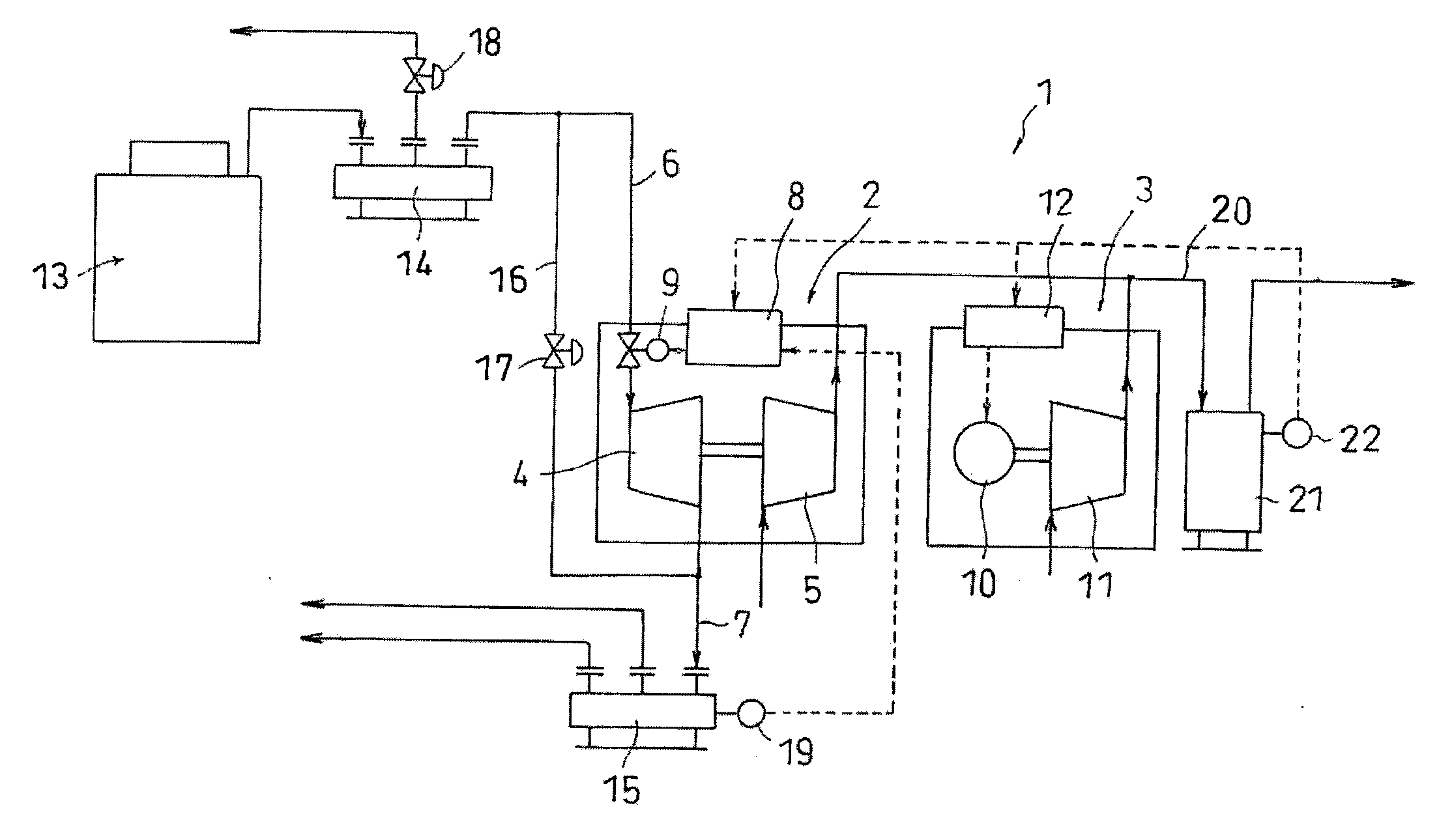
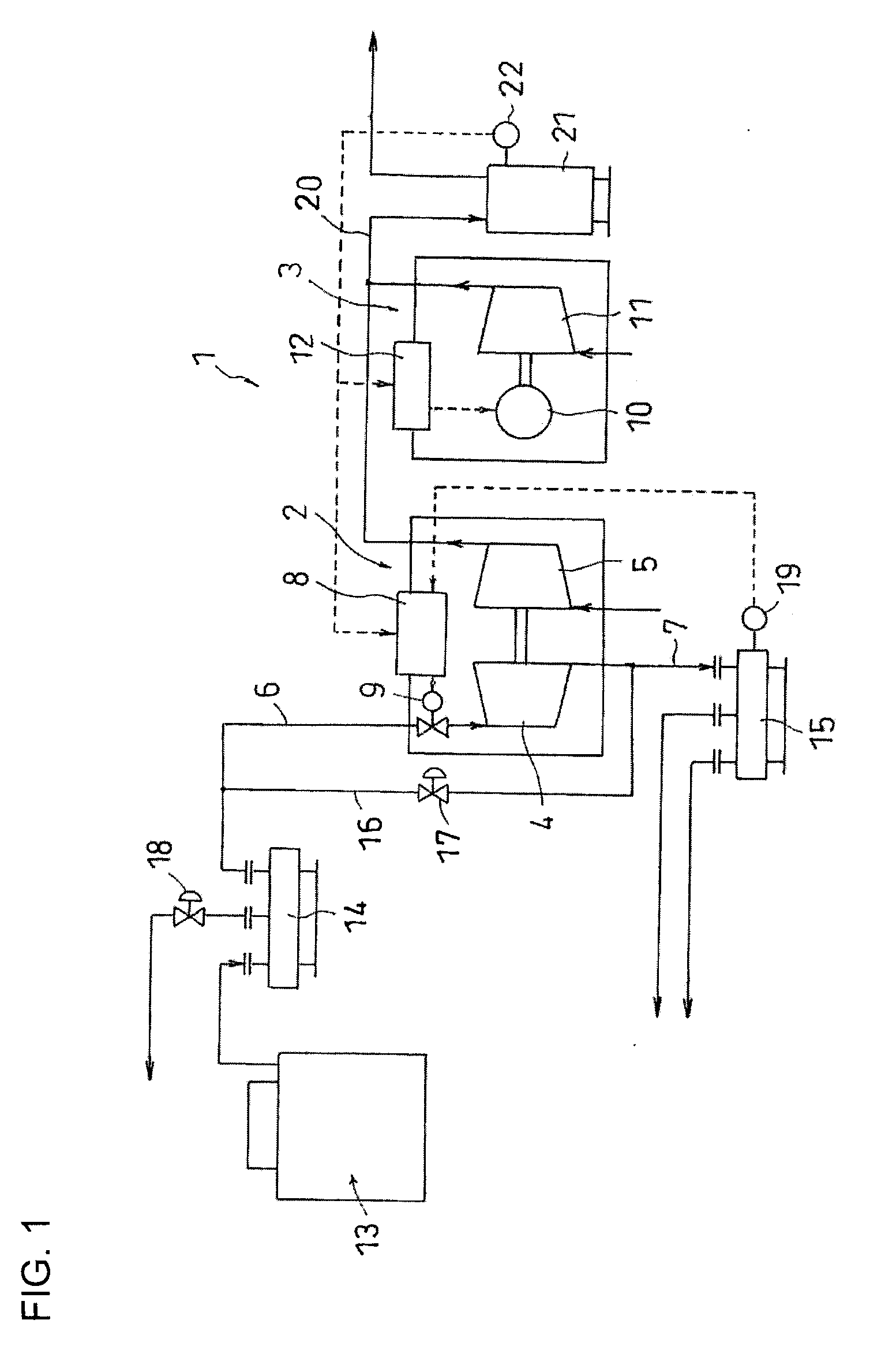
[0056]FIG. 1 is a schematic view showing one example of a steam system of the present invention. A steam system 1 of the present example includes a steam drive-type compressor unit 2, and an electric drive-type compressor unit 3.

[0057]The steam drive-type compressor unit 2 includes a steam engine (first prime mover) 4 that generates power when receiving steam, and an air compressor (first driven machine) 5 driven by the steam engine 4. The steam engine 4 may be a steam turbine, but is suitably a screw-type steam engine. The screw-type steam engine is a device in which the steam is introduced between screw rotors that engage with each other, and the steam expands while rotating the screw rotors with the steam thereby causing depressurization so that the power is obtained by the rotation of the screw rotor at the time.

[0058]The steam is supplied to the steam engine 4 throu...


PUM


Abstract

A steam engine and an electric motor are arranged, which respectively drives an air compressor. The compressed air from the air compressor is supplied to a compressed air using device through a common air tank. The steam is supplied to the steam engine through a steam supply path, and the steam used in the steam engine is supplied to a steam using device through a steam exhaust path. The steam pressure is monitored by a pressure sensor arranged in a steam header ahead of the steam exhaust path. The air pressure is monitored by a pressure sensor arranged in an air tank. A steam supply valve is controlled based on the steam pressure and the air pressure, and the electric motor is controlled based on the air pressure. The steam engine is preferentially driven over the electric motor by shifting the target value of the air pressure.

Description

BACKGROUND OF THE INVENTION[0001]1. Field of the Invention[0002]The present invention relates to a steam system that reduces power consumption by driving a compressor and the like using steam.[0003]The present application claims priority based on Japanese Patent Application No. 2008-055685 filed in Japan on Mar. 6, 2008, the contents of which are hereby incorporated by reference.[0004]2. Description of the Related Art[0005]Japanese Unexamined Patent Publication No. 63-45403 (Claims, FIG. 1, and P. 2, lower left column, lines 1 to 5 of publication) discloses a method of holding the back pressure of the steam on the steam flow-out side constant regardless of the load fluctuation by driving an air compressor (2) with a screw-type expander (1), and controlling the steam that flows into the screw-type expander (1) with an adjustable valve (10) at the time of load fluctuation of the air compressor (2) and controlling a by-pass valve (9) arranged between the steam flow-in side and the stea...

Claims


Application Information

Patent Timeline
Patent Type & Authority Applications(United States)
IPC IPC(8): F01K23/00
CPCF01D15/08F01K7/38F05D2220/31F02C6/16Y02E60/15F02C6/006Y02E60/16
Inventor YOSHINARI, YUJIOCHI, YASUOFURUKAWA, HIDEOTANAKA, YASUKUNIOKAMOTO, YUSUKEBABA, KAZUTAKA
Owner MIURA COMPANY LIMITED
Why Eureka
Try Eureka