Fuel injection control apparatus of internal combustion engine

a technology of control apparatus and internal combustion engine, which is applied in the direction of electric control, combustion engines, machines/engines, etc., can solve the problems of increasing the amount of nitrogen oxide, vibration or noise, and the pressure inside the cylinder drastically increases, so as to improve the exhaust emissions and stabilize the combustion

Inactive Publication Date: 2011-01-13
TOYOTA JIDOSHA KK
View PDF6 Cites 34 Cited by
  • Summary
  • Abstract
  • Description
  • Claims
  • Application Information

AI Technical Summary

Benefits of technology

[0037]With the present invention, with respect to a compression self-igniting internal combustion engine, when executing sub injection prior to main injection, by dividing the total sub injection amount required in this sub injection into a plurality of instances of divided sub injection, and suppressing penetration of fuel injected with the individual instances of divi

Problems solved by technology

When this flame propagation speed is large, the amount of fuel that burns at once becomes too great, pressure inside the cylinder drastically increases, and so vibration or noise occurs.
Also, in this

Method used


Image

  • Fuel injection control apparatus of internal combustion engine
  • Fuel injection control apparatus of internal combustion engine
  • Fuel injection control apparatus of internal combustion engine

Examples


Embodiment Construction

[0047]Following is a description of an embodiment of the invention based on the drawings. In the present embodiment, a case will be described in which the invention is applied to a common rail in-cylinder direct injection multi-cylinder (for example, inline four-cylinder) diesel engine (compression self-igniting internal combustion engine) mounted in an automobile.

[0048]Engine Configuration

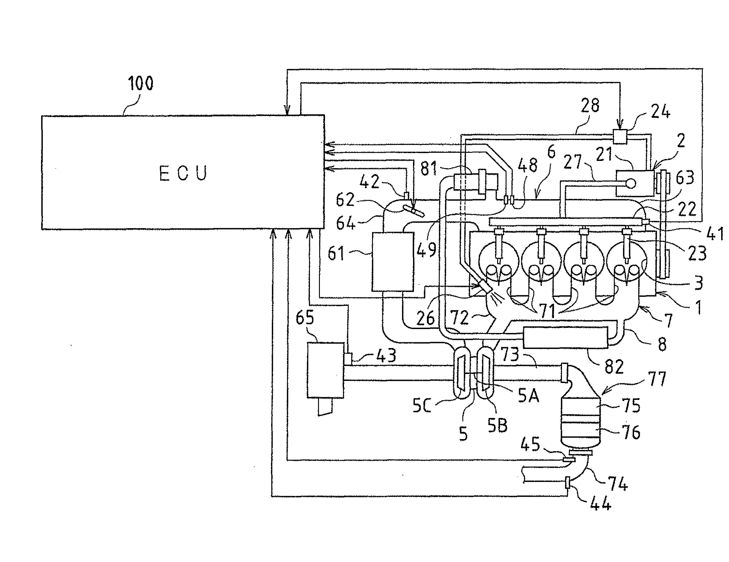
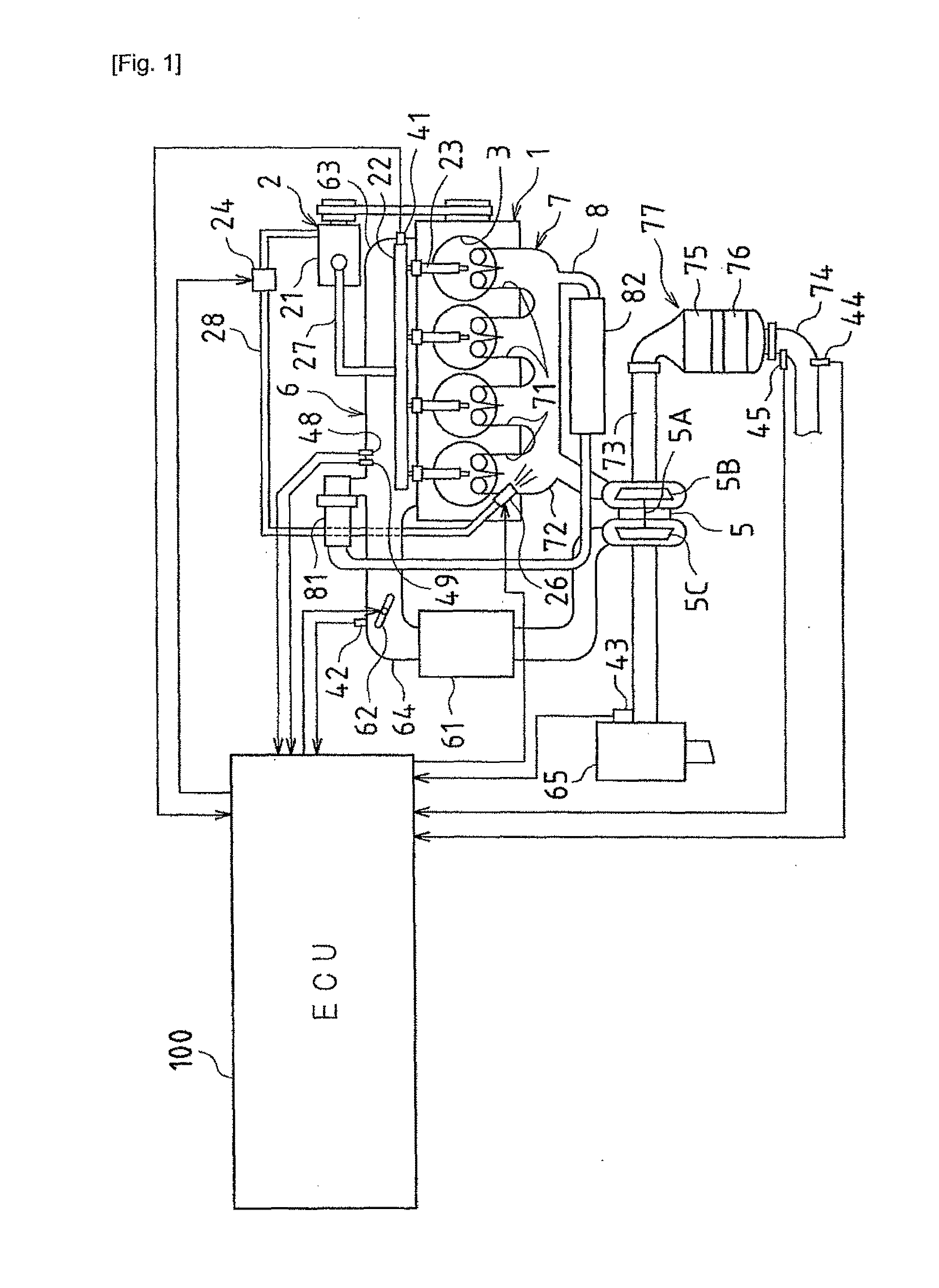
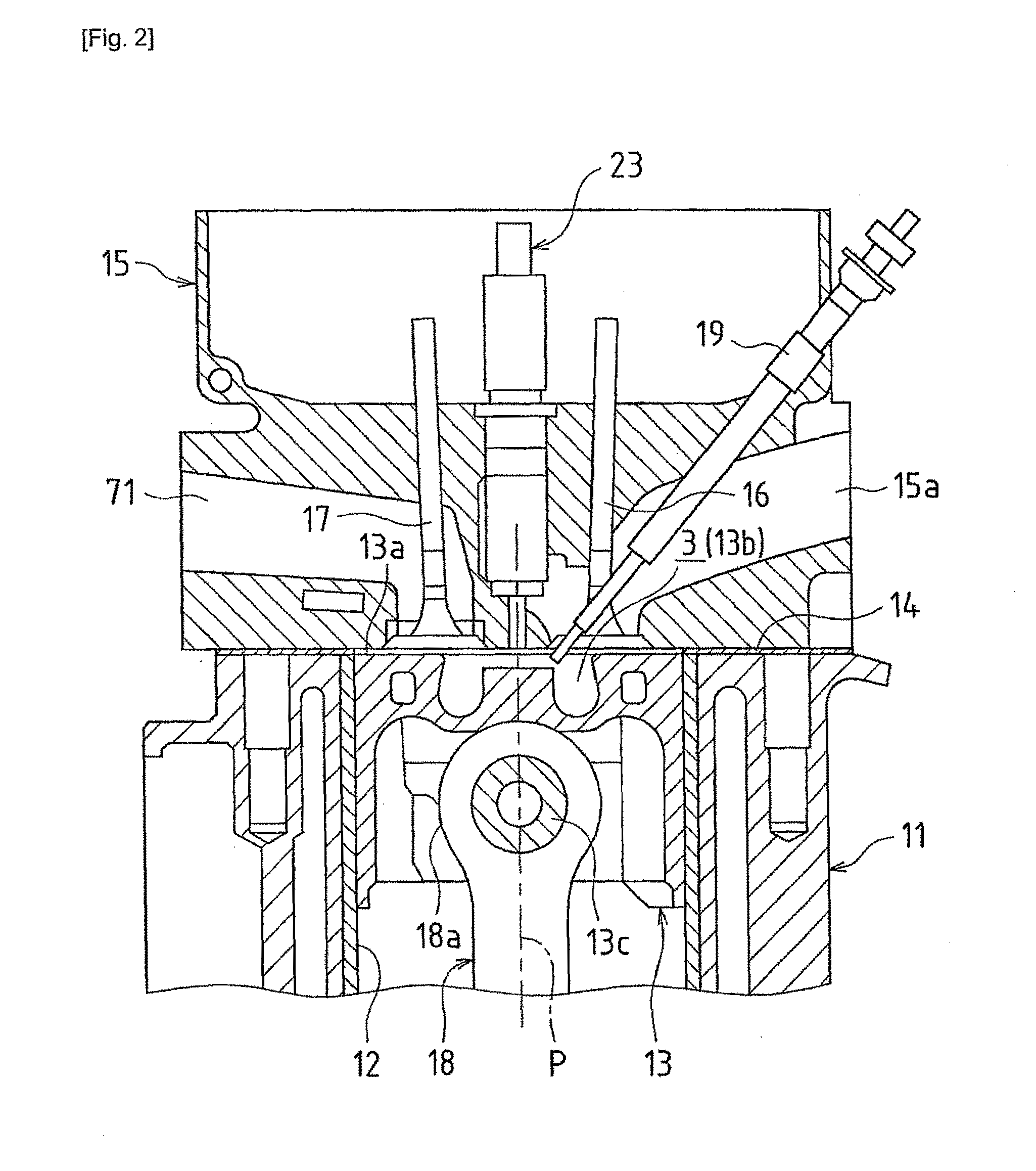
[0049]First, the overall configuration of a diesel engine (referred to below as simply the engine) according to the present embodiment will be described. FIG. 1 is a schematic configuration diagram of the engine 1 and a control system of the engine 1 according to this embodiment. FIG. 2 is a cross-sectional view that shows a combustion chamber 3 of the diesel engine and parts in the vicinity of the combustion chamber 3.

[0050]As shown in FIG. 1, the engine 1 according to this embodiment is a diesel engine system configured using a fuel supply system 2, combustion chambers 3, an intake system 6, an ...


PUM


Abstract

In one embodiment, a total pilot injection amount is calculated from the difference between a compressed gas temperature in a cylinder and a fuel self-ignition temperature. As pilot injection, a plurality of instances of divided pilot injection are performed, and by setting the injection amount per one instance of divided pilot injection to an injector minimum limit injection amount, each divided pilot injection amount is suppressed, and the penetration of fuel is suppressed to a low level so that attachment of fuel to a wall face is avoided, and also, fuel is caused to accumulate in the center portion of the cylinder.

Description

[0001]This is a 371 national phase application of PCT / JP2008 / 003595 filed 4 Dec. 2008, which claims priority to Japanese Patent Application No. 2008-004198 filed 11 Jan. 2008, the contents of which are incorporated herein by reference.FIELD OF THE INVENTION[0002]The present invention relates to a fuel injection control apparatus of an internal combustion engine represented by a diesel engine. More specifically, the present invention relates to, with respect to a compression self-igniting internal combustion engine in which it is possible to execute sub injection (also referred to below as pilot injection) prior to main injection from a fuel injection valve, improvement in the form of injection in this sub injection.BACKGROUND OF THE INVENTION[0003]As is conventionally known, in a diesel engine used as an automobile engine or the like, fuel injection control is performed that adjusts a fuel injection timing and a fuel injection amount from a fuel injection valve (also referred to bel...

Claims


Application Information

Patent Timeline
IPC IPC(8): F02B3/00
CPCF02D35/023F02D35/026F02D41/047Y02T10/44F02D41/403F02D2041/0015F02D2200/0414F02D41/402Y02T10/40
Inventor TERADA, YASUYUKINADA, MITSUHIROMATSUNAGA, AKIOTSUCHIYAMA, MAKIO
Owner TOYOTA JIDOSHA KK
Why Eureka
Try Eureka