
Lighting device

Active Publication Date: 2011-01-13
PANASONIC CORP
View PDF14 Cites 24 Cited by
  • Summary
  • Abstract
  • Description
  • Claims
  • Application Information

AI Technical Summary

Benefits of technology

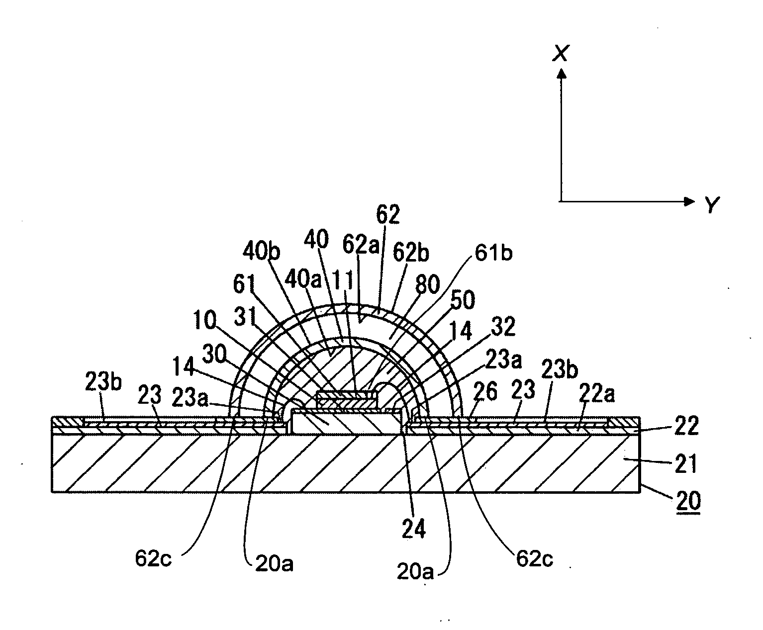
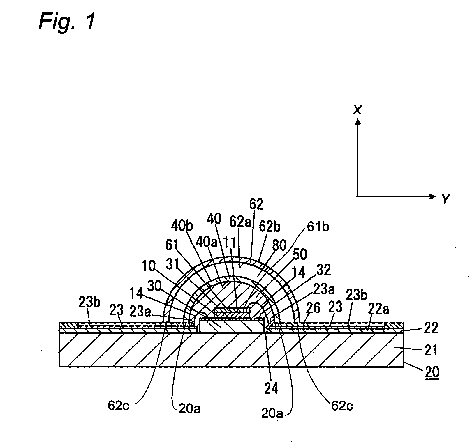
[0008]In this case, the second color conversion member is disposed on the mounting substrate such that the second color conversion member covers the first color conversion member. Therefore, it is possible to prevent the color unevenness of the light which is emitted from the lighting device. In addition, the first color conversion member is directly disposed on the light emitting surface of the LED chip. Therefore, it is possible to transfer the heat of the first color conversion member to the mounting substrate through the LED chip. That is, it is possible to prevent the temperature quenching which is caused by the increase of the temperature of the first phosphor and the second phosphor.
[0010]In this case, the first amount of the heat generation of the heat which is generated in the first color conversion member is greater than the second amount of the heat generation of the heat which is generated in the second color conversion member. Therefore, it is possible to prevent the temperature increase of the second phosphor of the second color conversion member. Furthermore, the heat which is generated in the first phosphor of the first color conversion member is transferred to the mounting substrate through the LED chip. Consequently, it is possible to prevent the temperature quenching which is caused by the temperature increase of the first phosphor and the second phosphor.
[0013]In this case, the air layer prevents the light which is given off by the second phosphor from traveling toward the cap. Therefore, it is possible to obtain the lighting device comprising the second color conversion member being configured to give off the light which is emitted to the outside of the second color conversion member. Furthermore, it is possible to increase options of the materials of the first phosphor and the second phosphor.
[0015]In this case, the light which is emitted from the LED chip and which is transmitted through the first color conversion member is emitted to the second color conversion member efficiently. Similarly, the light which is given off from the first phosphor is emitted to the second color conversion member through the emission surface effectively. Therefore, the light which is given off from and through the first color conversion member is effectively emitted to the second color conversion member. Furthermore, it is possible to prevent the temperature increase of the first color conversion member.

Problems solved by technology

Therefore, the heats of both the first color conversion member and the second color conversion member are not capable of being released effectively.
Similarly, a temperature increase also causes the temperature quenching.
That is, the prior lighting device has a problem of the chromaticity shift which is caused when the balance between the light emitted from the LED chip and the light which is given off from each the color conversion member is disrupted.
In addition, the prior lighting device also has a problem of the reduction of the light output which is caused when the balance between the light emitted from the LED chip and the light which is given off from each the color conversion member is disrupted.

Method used


Image

  • Lighting device
  • Lighting device
  • Lighting device

Examples


first embodiment

[0032]The lighting device in the present embodiment is explained with attached drawings. It is noted that the X direction indicated by an arrow shows an upper direction of the lighting device. Y direction indicated by an arrow shows a left direction of the lighting device. FIG. 1 shows the lighting device in this embodiment. The lighting device comprises an LED chip 10, a mounting substrate 20, a first color conversion member 61, and a second color conversion member 62. The LED chip 10 has a light emitting surface 11. The mounting substrate 20 is shaped to have a mounting surface for mounting the LED chip 10. The first color conversion member 61 shaped to have a sheet shape. The first color conversion member 61 is directly disposed on the light emitting surface 11 of the LED chip 10. The first color conversion member 61 is made of a first light transmissive material with a first phosphor. The first phosphor is excited by the light which is emitted from the LED chip 10 so as to give ...

second embodiment

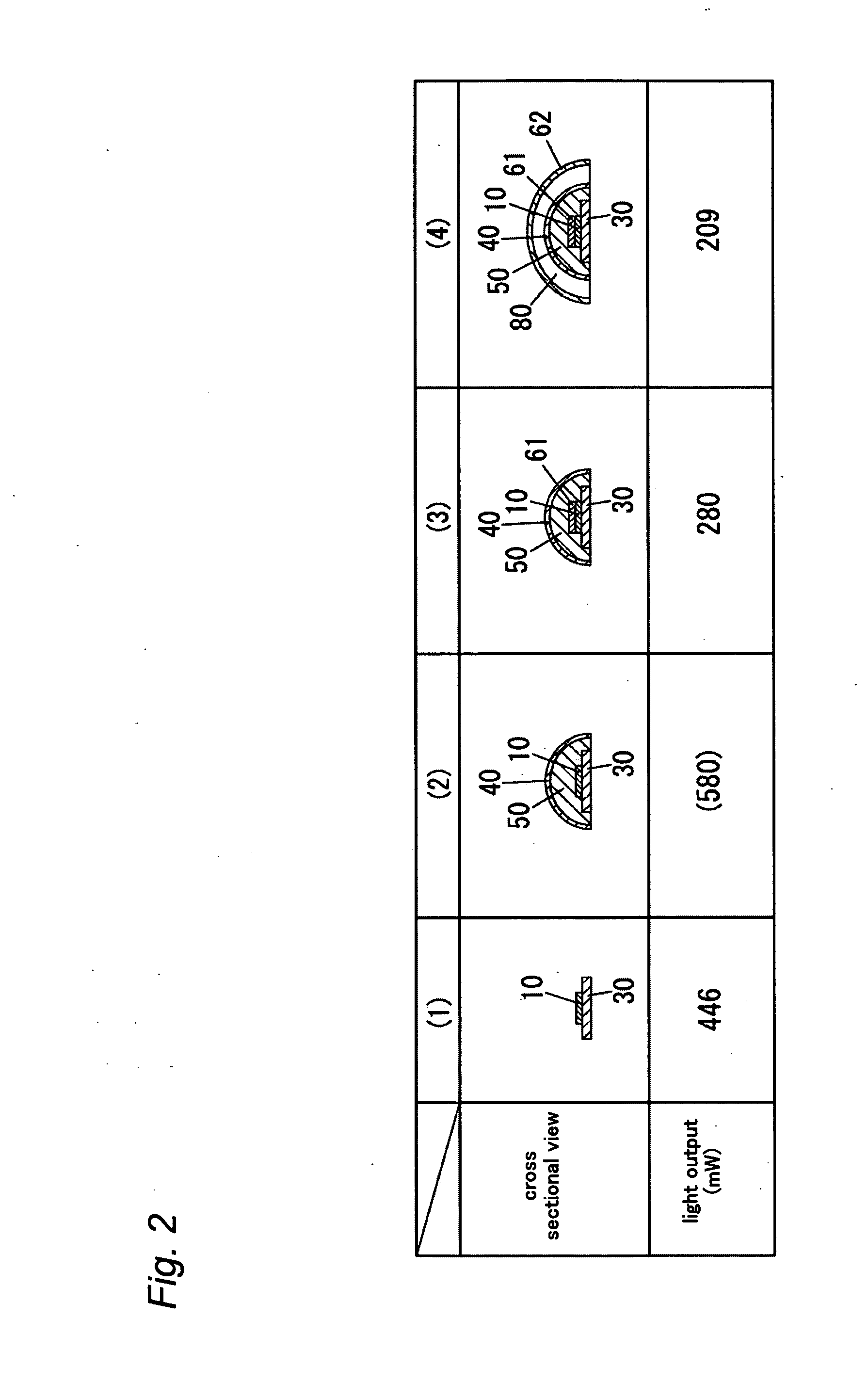
[0057]The lighting device in this embodiment has basic components which are in common with the basic components of the lighting device in the first embodiment. In this embodiment, the lighting device in this embodiment is different from the lighting device in the first embodiment in the first phosphor and the second phosphor. That is, in this embodiment, the first phosphor of the first color conversion member 61 in FIG. 1 is realized by a red phosphor. The second phosphor of the second color conversion member 62 is realized by a green phosphor. In contrast, similar to the first embodiment, the amount of the first phosphor and the amount of the second phosphor are determined such that the amount of the heat generation of the first color conversion member 61 is greater than the amount of the heat generation of the second color conversion member 62. In the lighting device of this embodiment, FIG. 3 shows a measurement result of the light output in the manufacture process of the lightin...

third embodiment

[0061]A lighting device in this embodiment has basic components which are in common with the basic components of the lighting device in the first embodiment. The lighting device of this embodiment is different from the lighting device of the first embodiment in the first phosphor and the second phosphor. That is, the first phosphor of the first color conversion member 61 is the red phosphor in addition to the green phosphor. The second phosphor of the second color conversion member 62 is also the red phosphor in addition to the green phosphor.

[0062]That is, in the lighting device of this embodiment, the second color conversion member 62 is used as a color matching layer for matching the color of the light. Therefore, it is possible to decrease the amount of the heat generation in the second color conversion member 62, compared with the amount of the heat generation in the first color conversion member 61. This results in a prevention of the temperature increase of the second phospho...


PUM


Abstract

A lighting device comprising an LED chip having a light emitting surface, and being configured to emit a light from the light emitting surface, a mounting substrate being configured to mount the LED chip, a first color conversion member comprising a first light transmissive material and a first phosphor, the first phosphor being excited by the light which is emitted from the LED chip, thereby giving off a first light having a wavelength which is longer than a wavelength of the light emitted from the LED chip, the first color conversion member being directly disposed on the light emitting surface of the LED chip, a second color conversion member comprising a second light transmissive material and a second phosphor, the second phosphor being excited by the light which is emitted from the LED chip, thereby giving off a second light having a wavelength which is longer than the wavelength of the light emitted from the LED chip, the second color conversion member being shaped to have a dome-shape, wherein the LED chip and the first color conversion member are disposed between the mounting substrate and the second color conversion member.

Description

TECHNICAL FIELD[0001]This invention relates to a lighting device using an LED chip (light emitting diode chip).BACKGROUND ART[0002]Japanese patent application publication No. 2007-35885 discloses a prior lighting device. The prior lighting device comprises a combination of an LED chip and a phosphor, whereby the prior lighting device outputs light having a desired color. The desired color of light is, such as, a white light.[0003]The prior lighting device comprises an LED chip, a mounting substrate, a light transmissive sealing member, a first color conversion member, and a second light conversion member. The mounting substrate is realized by a ceramic substrate. The mounting substrate is provided for mounting the LED chip. The light transmissive sealing member is made of a light transmissive sealing material such as silicone resin. The light transmissive sealing member is shaped to have a hemisphere shape, whereby the light transmissive sealing member is cooperative with a mounting...

Claims


Application Information

Patent Timeline
IPC IPC(8): H01L33/48H01L33/50H01L33/54H01L33/56H01L33/62
CPCH01L33/504H01L33/507H01L33/58H01L2933/0091H01L2224/48091H01L2924/00014
Inventor SUZUKI, TOMONORITANAKA, KENICHIROURANO, YOUJI
Owner PANASONIC CORP
Learn More