Supercharge Your Innovation With Domain-Expert AI Agents!

Method and system for a more efficient and dynamic waste heat recovery system

a waste heat recovery and dynamic technology, applied in the direction of electric generator control, rotors, machines/engines, etc., can solve the problems of increasing the cost of operating an automobile for transportation, affecting the efficiency of fuel consumption, and overweight traditional automobiles, so as to achieve the effect of more energy

Inactive Publication Date: 2011-01-13
TOYOTA MOTOR ENGINEERING & MANUFACTURING NORTH AMERICA
View PDF65 Cites 26 Cited by
  • Summary
  • Abstract
  • Description
  • Claims
  • Application Information

AI Technical Summary

Benefits of technology

The present invention is a system and method for efficiently capturing and utilizing waste heat in an automobile. The system includes a heat exchanger with variable pitch impellers and a generator with dynamically activated windings. The impellers rotate the shaft connected to the generator, and the pitch of the impellers can be adjusted to capture more energy from the vapor stream. The windings can be activated based on the energy requirements of the automobile's energy storage unit and accessories. The system allows for more efficient energy generation and better match with the automobile's energy needs. The invention can be applied to automobiles with traditional combustion engines or electric engines.

Problems solved by technology

With global energy prices increasing, the cost of operating an automobile for transportation also increases.
The cost of operating an automobile may be affected by its weight and also fuel consumption efficiencies.
However, traditional automobiles may be overweight and do not fully and efficiently utilize the fuel consumed by the automobile.
However such methods and systems may not fully capture the energy potential of the vapor stream where the vapor stream is at certain conditions such as a low velocity.
Furthermore, such methods and systems may generate too much energy, requiring that the energy be dissipated by other means, such as through a resistor.
This can be problematic with either too little energy being generated or too much energy being generated.

Method used


Image

  • Method and system for a more efficient and dynamic waste heat recovery system
  • Method and system for a more efficient and dynamic waste heat recovery system
  • Method and system for a more efficient and dynamic waste heat recovery system

Examples


Embodiment Construction

[0022]Apparatus, systems and methods that implement the embodiments of the various features of the present invention will now be described with reference to the drawings. The drawings and the associated descriptions are provided to illustrate some embodiments of the present invention and not to limit the scope of the present invention. Throughout the drawings, reference numbers are re-used to indicate correspondence between referenced elements.

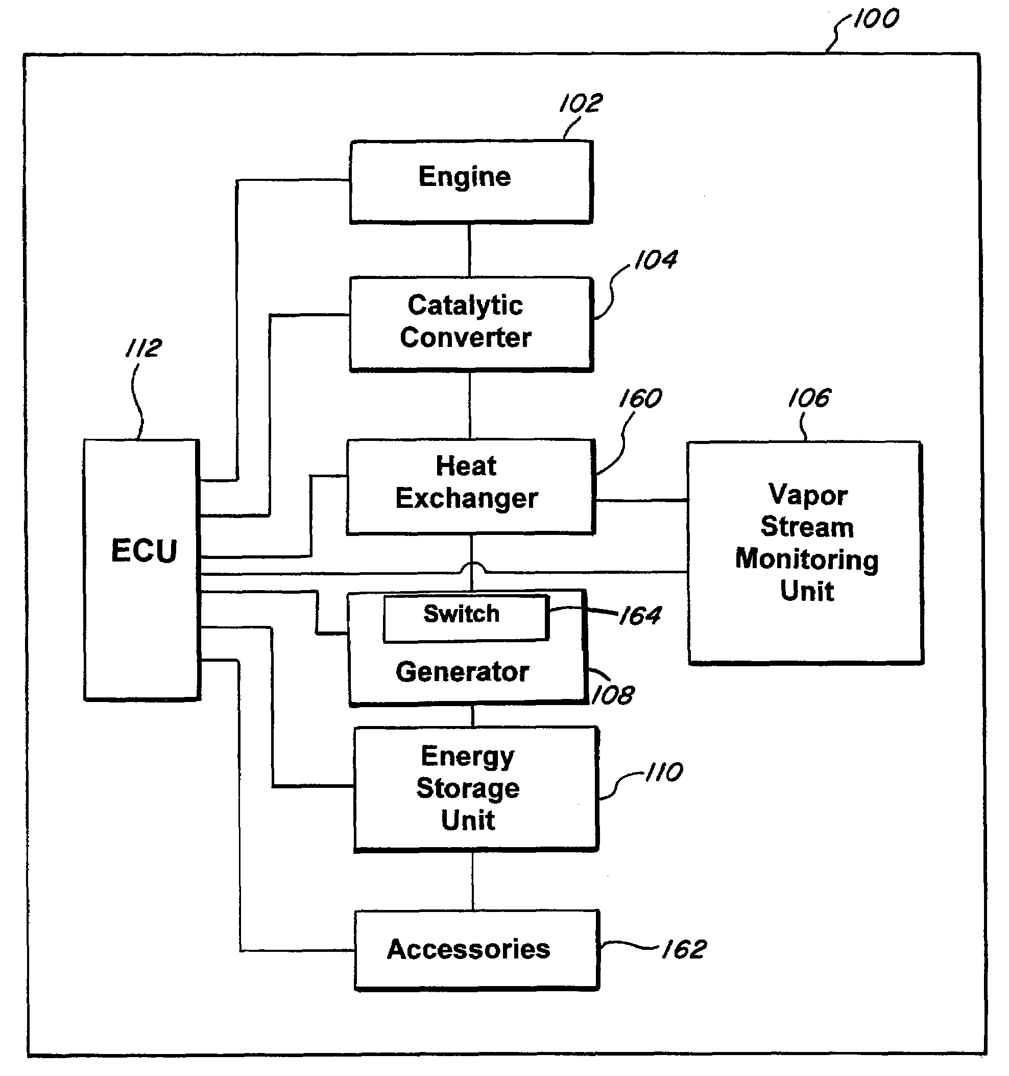
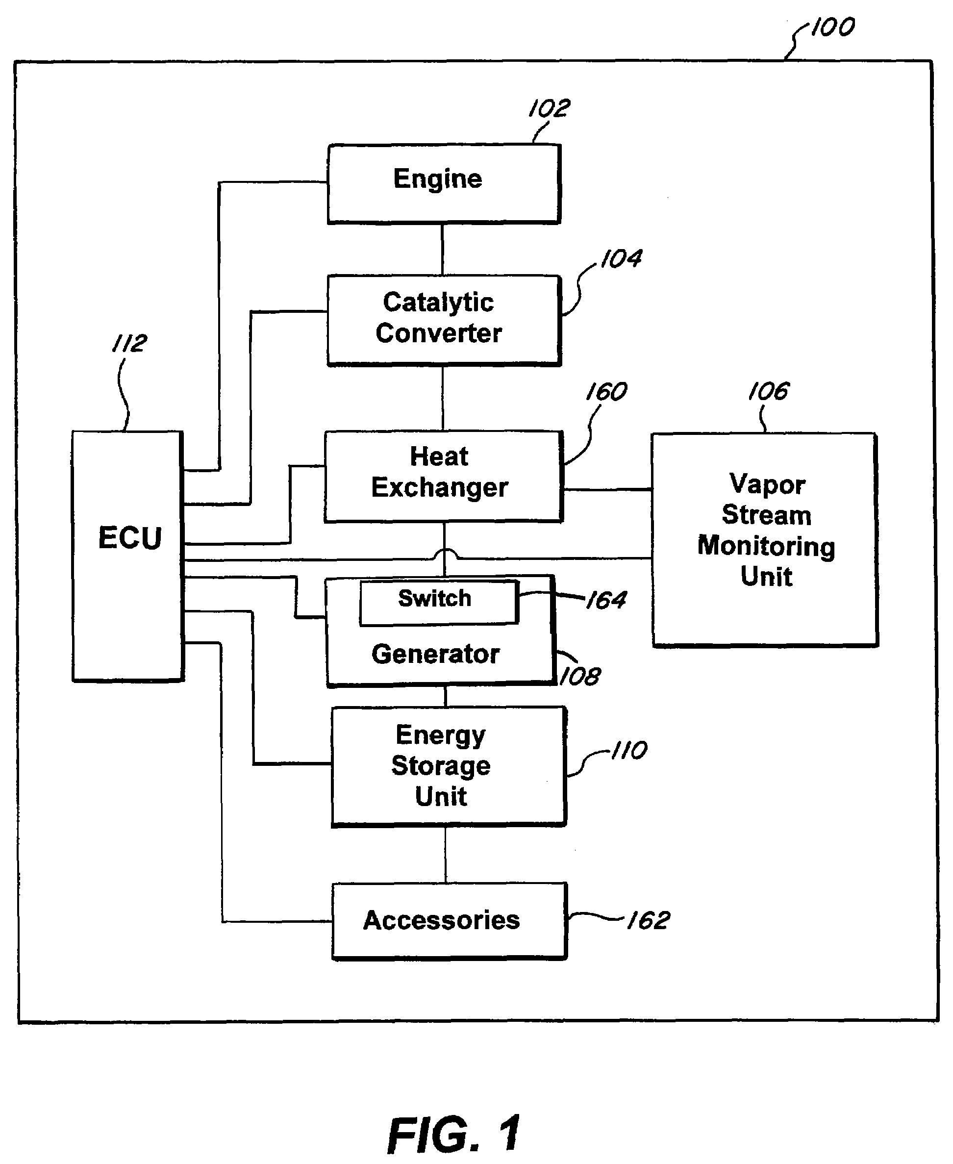
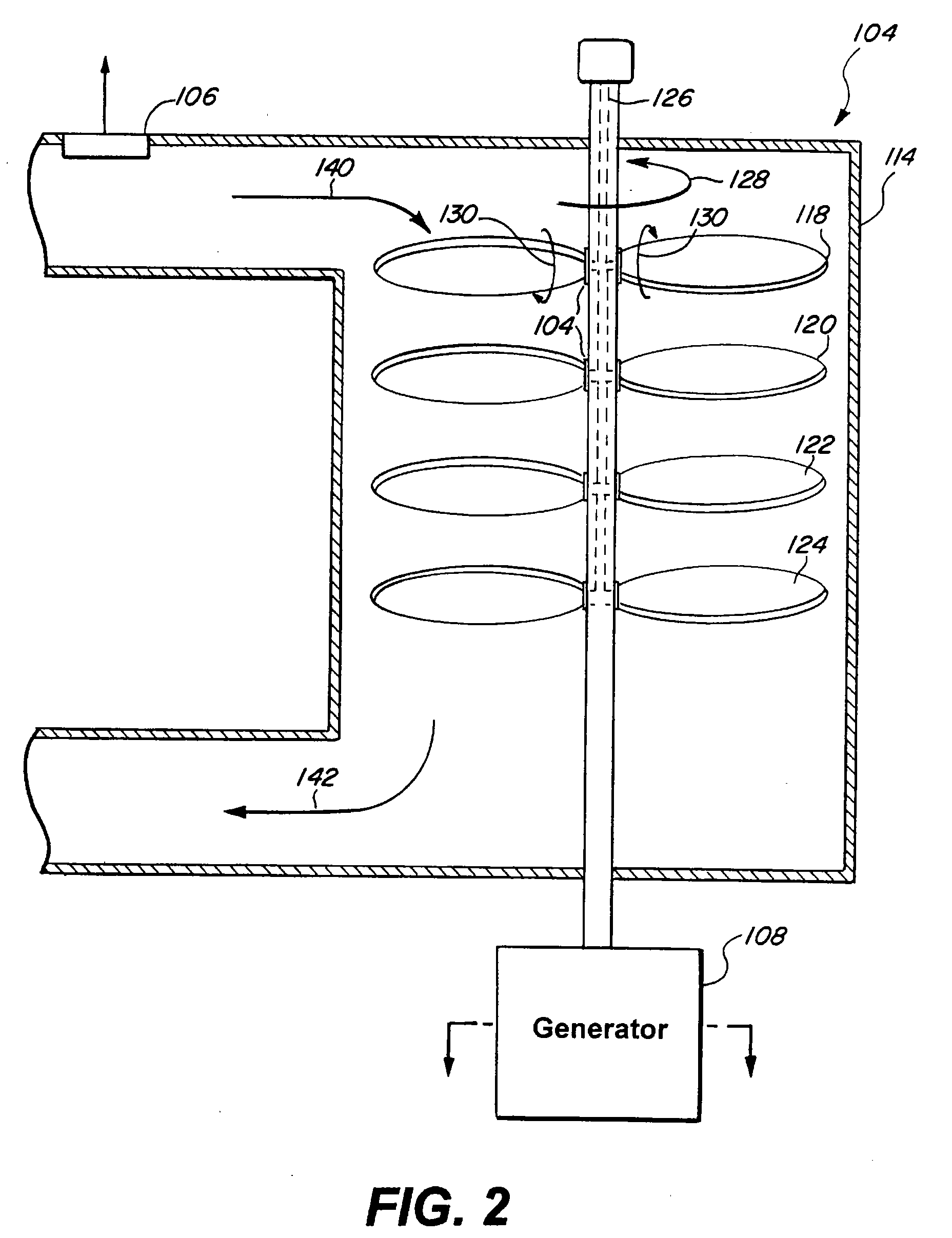
[0023]As seen in FIG. 1, the present invention can be embodied in an automobile 100. The automobile 100 can be, for example, a gasoline powered automobile, an automobile with a hybrid engine, a natural gas powered automobile, an ethanol powered automobile, a propane powered automobile, a fossil fuel powered automobile, an automobile with an internal combustion engine, or any other type of automobile with any type of engine. The automobile 100 can include, for example, an engine 102, a heat exchanger 104, a catalytic converter 160, a vapor stre...


PUM


Abstract

The present invention relates to a method and system for a more efficient and dynamic waste heat recovery system in an automobile. The present invention includes a heat exchanger connected to a generator. The heat exchanger includes variable pitch impellers attached to and rotating a shaft. The pitch of the impellers can be dynamically varied and the impellers can also be staggered. The generator includes a rotor connected to the shaft. The rotor rotates within a stator when the shaft rotates. The stator includes windings with different thicknesses and different turn ratios allowing for generation of different energy levels by each of the windings. Each of the windings can be dynamically activated. The pitch of the impellers can be dynamically altered and the windings can be dynamically activated depending on energy requirements of an energy storage unit and / or accessories in the automobile.

Description

BACKGROUND[0001]1. Field of the Invention[0002]The present invention relates to a method and system for a more efficient waste heat recovery system. More specifically, the present invention relates to a method and system for a more efficient and dynamic waste heat recovery system in an automobile.[0003]2. Description of the Related Art[0004]With global energy prices increasing, the cost of operating an automobile for transportation also increases. The cost of operating an automobile may be affected by its weight and also fuel consumption efficiencies. However, traditional automobiles may be overweight and do not fully and efficiently utilize the fuel consumed by the automobile. For example, waste heat in the form of vapor stream may be generated during the consumption of fuel by a motor. Conventional methods and systems have attempted to generate energy from the vapor stream. However such methods and systems may not fully capture the energy potential of the vapor stream where the va...

Claims


Application Information

Patent Timeline
Patent Type & Authority Applications(United States)
IPC IPC(8): F02D29/06H02K23/36H02P9/00F01K23/06F01D5/02F01N3/10
CPCF01K15/02F01K23/065Y02T10/16F01N2240/02H02K7/1823F01N5/02Y02T10/12
Inventor SAMUEL, WOODSON WAYNE
Owner TOYOTA MOTOR ENGINEERING & MANUFACTURING NORTH AMERICA
Features
  • R&D
  • Intellectual Property
  • Life Sciences
  • Materials
  • Tech Scout
  • Unparalleled Data Quality
  • Higher Quality Content
  • 60% Fewer Hallucinations
Learn More