Scanning array for obstacle detection and collision avoidance

a technology of collision avoidance and scanning array, which is applied in wave based measurement systems, instruments, and using reradiation. it can solve problems such as cable strikes, antennas, pylons,

Inactive Publication Date: 2011-01-13
INTELLEX LLC
View PDF53 Cites 42 Cited by
  • Summary
  • Abstract
  • Description
  • Claims
  • Application Information

AI Technical Summary

Benefits of technology

[0008]These and other goals are achieved by the scanning array of the invention. The scanning array of the invention is a device which may be mounted on a vehicle such as a helicopter, an airplane, or a ground vehicle such as a tank, mobile artillery piece, humvee or armored personal personnel carrier. The scanning array is a device which sends out a beam in a generally hemispherical shape. As the energy beam encounters objects within its range, a part of the energy is reflected back to the scanning array, is received by sensors, is interpreted by a computational device and information about the topography or nearby obstacles is presented to the operator of the vehicle. In the case of a helicopter, one piece of data which is of primary importance is a scan to detect collision obstacles, such as wires, power lines, t...

Problems solved by technology

The problem of scanning an area for objects at night or in bad weather has long been a problem for all kinds of vehicles.
For instance, a helicopter striking obstacles such as wires has been a problem throughout the history of helicopters.
Other obstacles can include pylons, radio masts, guy wires, transmission wires, antennas, and cables, and are very serious problems, since many helicopter missions involve flying at low altitudes, or landing in makeshift landing zones.
Most helicopter crashes occur during landing, often in inclement weather.
Combine these issues with above ground electrical wires and powe...

Method used


Image

  • Scanning array for obstacle detection and collision avoidance
  • Scanning array for obstacle detection and collision avoidance
  • Scanning array for obstacle detection and collision avoidance

Examples


Embodiment Construction

[0049]While the invention is susceptible of various modifications and alternative constructions, certain illustrated embodiments thereof have been shown in the drawings and will be described below in detail. It should be understood, however, that there is no intention to limit the invention to the specific form disclosed, but, on the contrary, the invention is to cover all modifications, alternative constructions, and equivalents falling within the spirit and scope of the invention as defined in the claims.

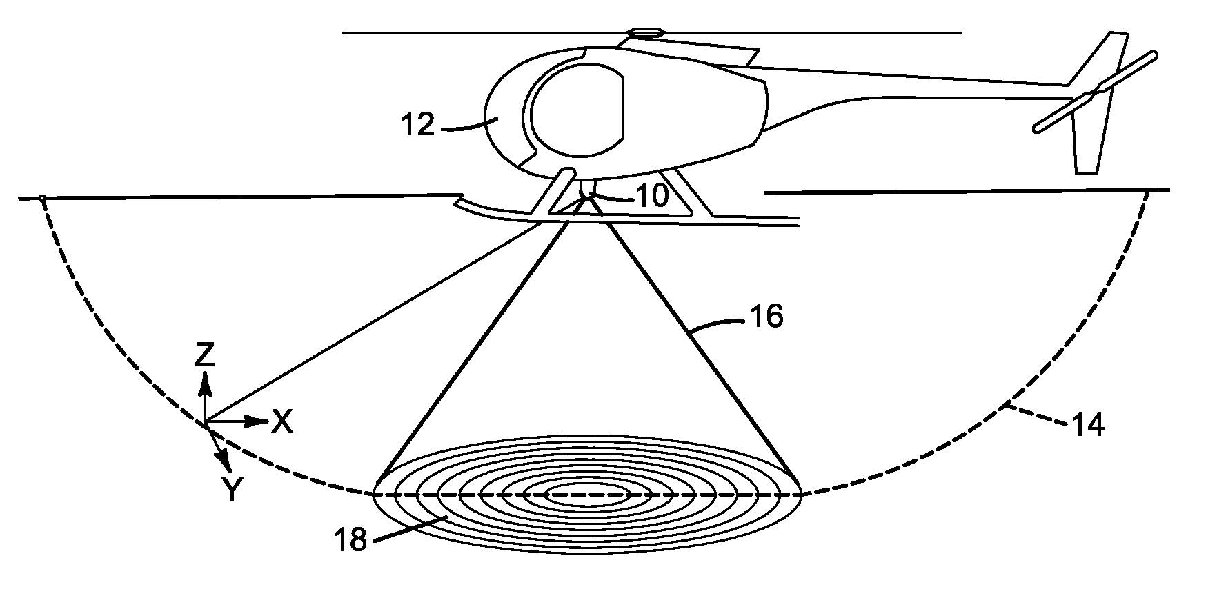
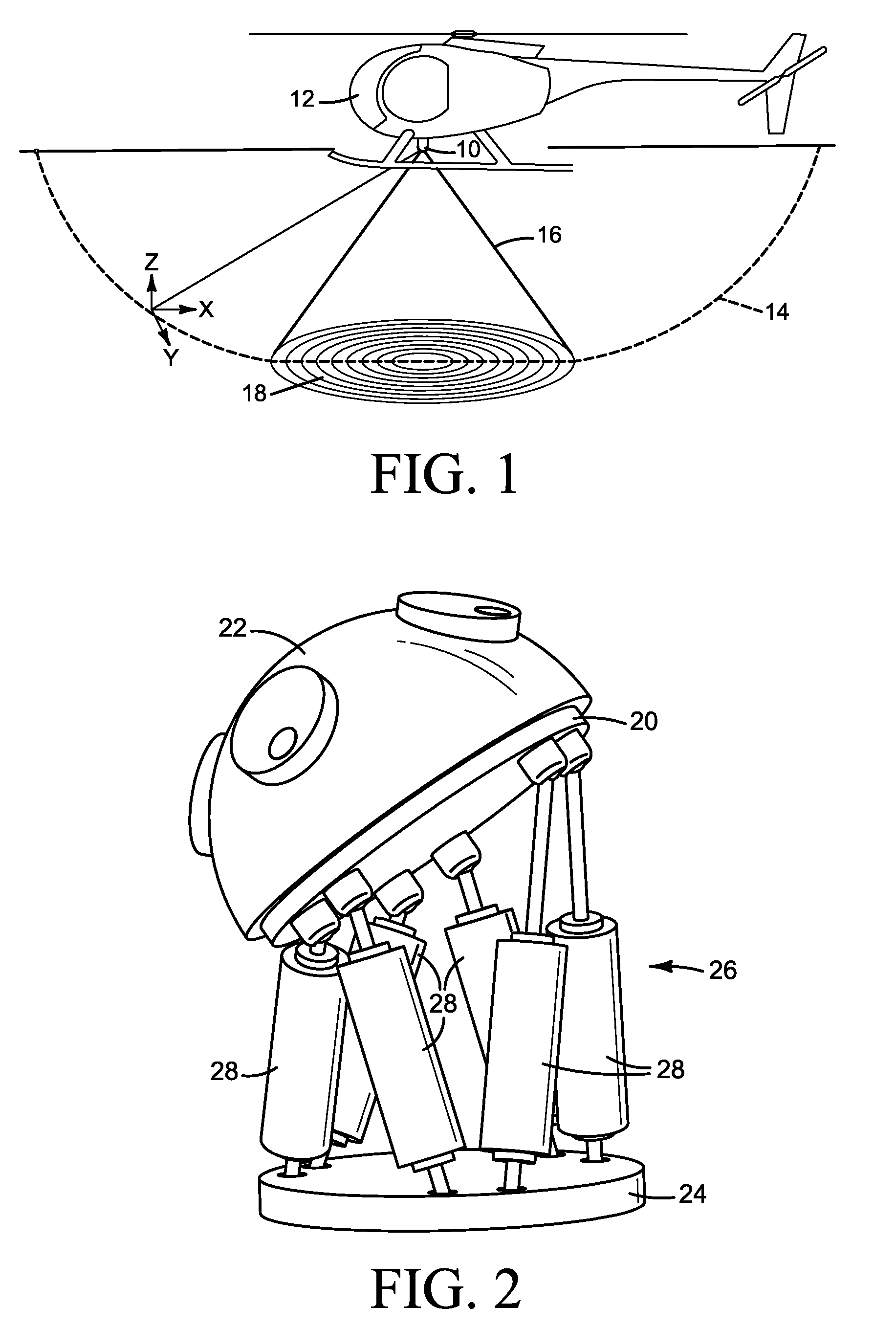
[0050]Several preferred embodiments of the scanning array of the invention are shown in FIGS. 1-18. FIG. 1 shows an example of the scanning array 10 of the invention, attached to a vehicle 12, which in this case is a helicopter. As noted above, the The scanning array can also be a stand alone unit, or attached to a building, or used with any number of different kinds of vehicles, such as helicopters, fixed wing aircraft, jeeps, tanks, trucks, and watercraft such as surface vehicle...


PUM

PropertyMeasurementUnit
Distanceaaaaaaaaaa
Wavelengthaaaaaaaaaa
Energyaaaaaaaaaa

Abstract

This scanning array scans an area around the array for nearby objects, collision obstructions, and terrain topography. The scanning array can scan for sounds emitted by objects in the vicinity of the scanning array, passive energy receipt sources, or it can also send out an energy beam and scan for reflections from objects within the energy beam. The energy beam can be optical, laser, radar or other energy emitting sources. The scanning array of the invention can be used for helicopter detection and avoidance of collision risk and can be used for other scanning purposes. Scanning of an entire hemisphere or greater is accomplished by manipulating the scanner platform through the coordination of either linear actuators or gimbals so as to produce nutation without rotation. This motion allows transceivers to be directly coupled to transmitting and sensing modules without the losses associated with slip rings and other coupling devices.

Description

PRIORITY / CROSS-REFERENCE TO RELATED APPLICATIONS[0001]This application claims the priority date of two provisional application entitled Articulating Platform for Mounting and Aiming Multiple Transmitters, Receivers and or Transceivers of Light and Other Energy Media filed on Dec. 8, 2008 with application Ser. No. 61 / 120,780, and of application Ser. No. 61 / 201,826 filed Dec. 16, 2008, both of which disclosures are incorporated here by reference.BACKGROUND OF THE INVENTION[0002]The invention generally relates to an apparatus for scanning a hemisphere in space, and more particularly to an apparatus for using an energy beam and reflected energy receivers to scan a hemisphere in space to detect obstacles to the flight of a helicopter, aircraft, or other vehicle.[0003]The problem of scanning an area for objects at night or in bad weather has long been a problem for all kinds of vehicles. For instance, a helicopter striking obstacles such as wires has been a problem throughout the history ...

Claims


Application Information

Patent Timeline
IPC IPC(8): G01S13/06G01V1/00G01B11/14G01S17/933
CPCG01S17/933G01S7/4818G01S7/4813G01V99/00
Inventor SHAFFER, JAMES E.
Owner INTELLEX LLC
Why Eureka
Try Eureka