Imaging Device and Image Reproduction Device

a technology of image reproduction device and image taker, which is applied in the field of image taker and image reproduction device, can solve the problem of difficult image taking by image taker to communicate with objects

Active Publication Date: 2011-01-13
XACTI CORP
View PDF18 Cites 58 Cited by
  • Summary
  • Abstract
  • Description
  • Claims
  • Application Information

AI Technical Summary

Benefits of technology

[0021]According to the present invention, it is possible to provide an imaging device that is able to obtain an image of an object of interest along intention of an image taker without concentrating on the image taking operation so much. Besides, it is possible to provide an image reproduction device that is able to reproduce a moving image of an object of interest along intention of the image taker without concentrating on the image taking operation so much in an image taking time.
[0022]The meaning and advantages of the present invention will be more apparent from the embodiments described below. Here, the following embodiments are each an embodiment of the present invention and the present invention and the meaning of a term of each constituent component are not limited to those described in the following embodiments.

Problems solved by technology

Accordingly, the image taker had to concentrate on the image taking and it was hard for the image taker to take an image communicating with the object of interest or paying attention to other things.

Method used


Image

  • Imaging Device and Image Reproduction Device
  • Imaging Device and Image Reproduction Device
  • Imaging Device and Image Reproduction Device

Examples


first embodiment

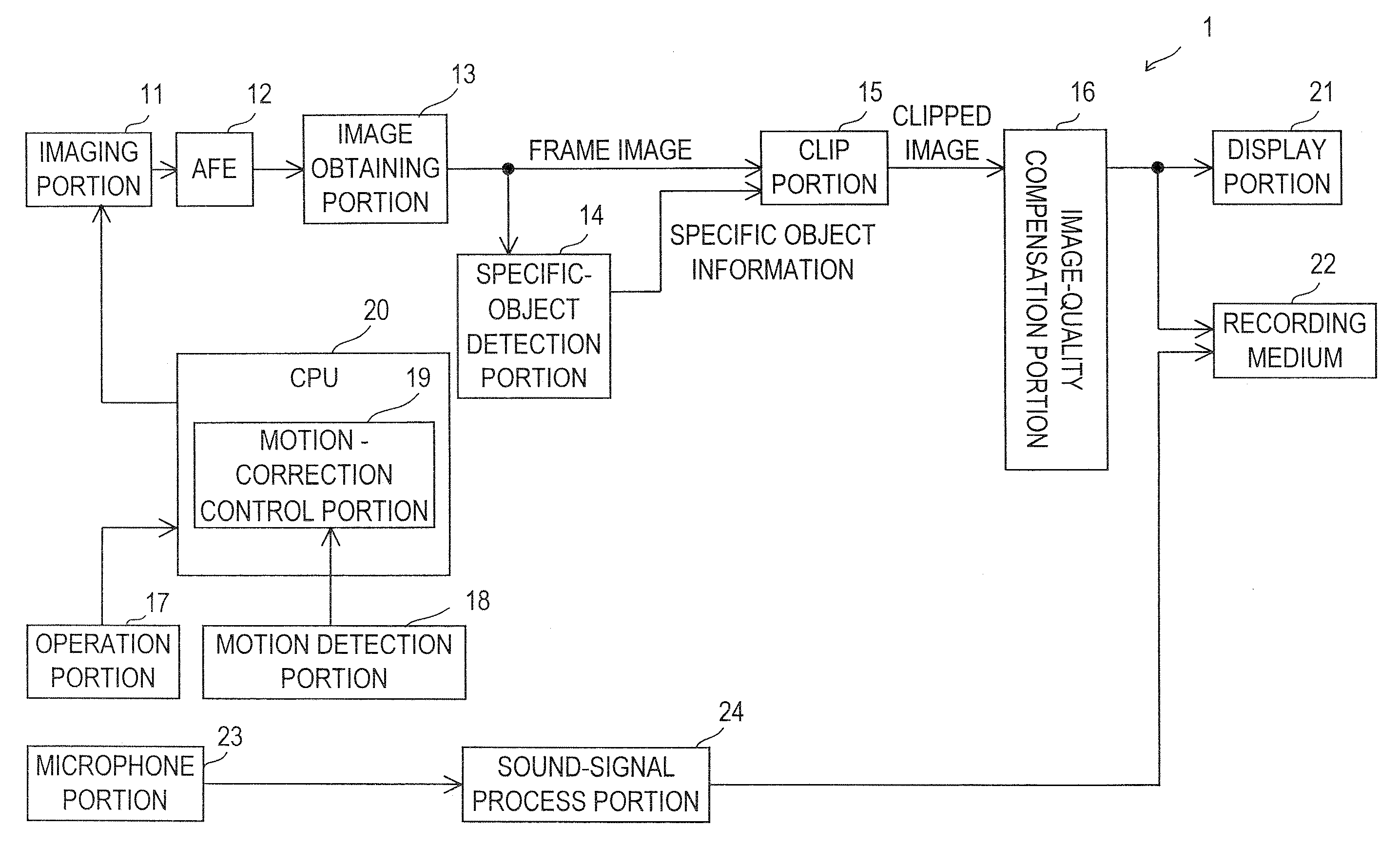
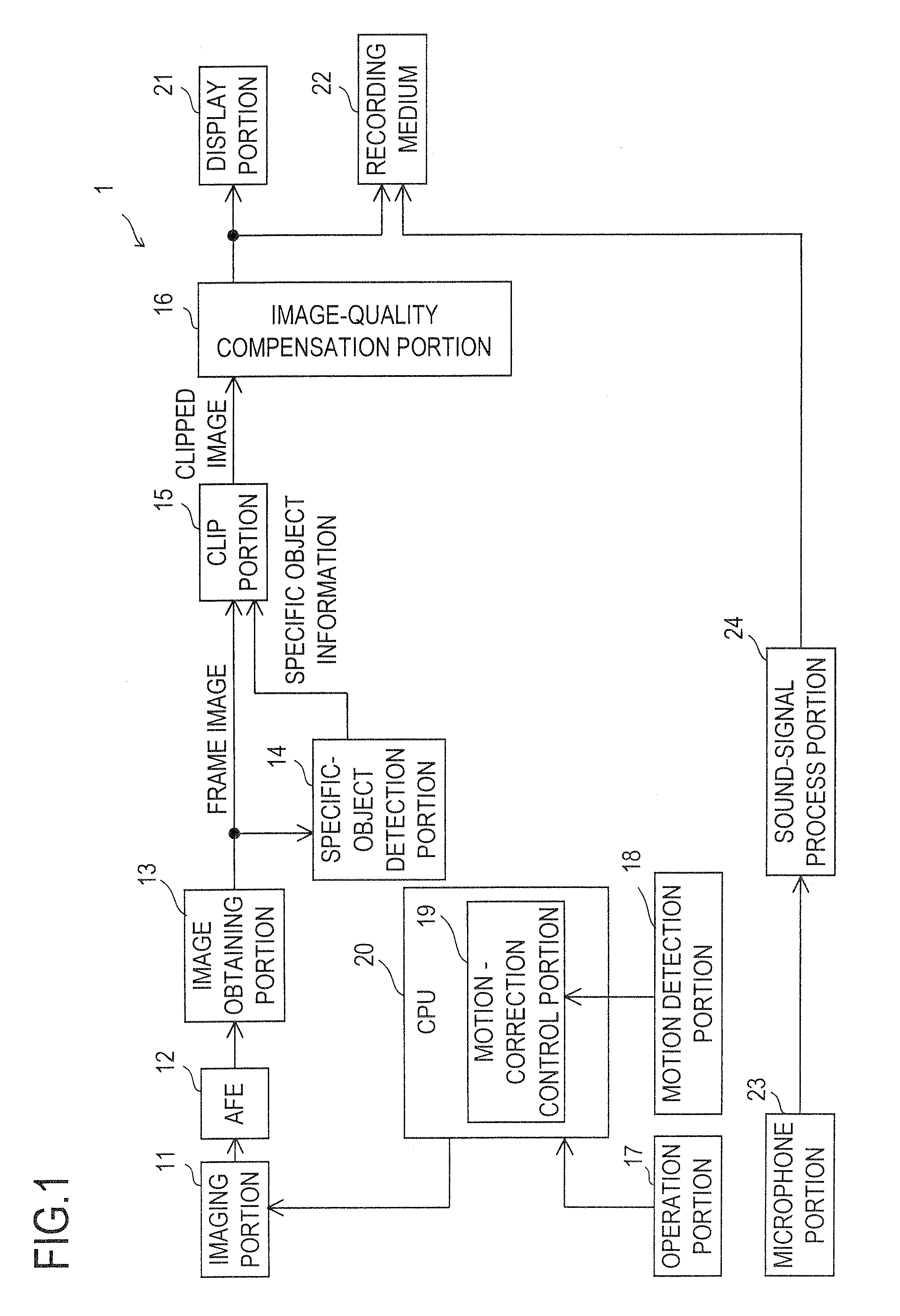
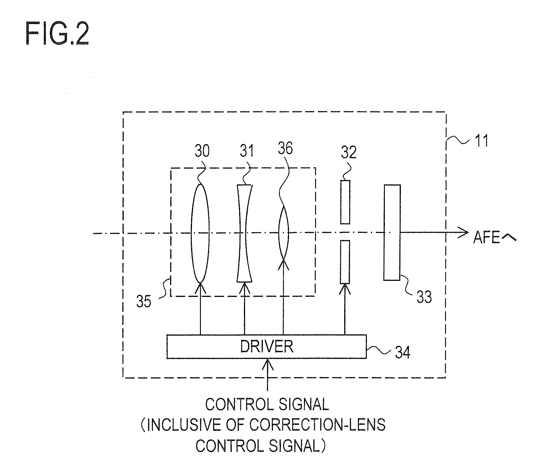
[0060]First, a first embodiment of the present invention is described. FIG. 1 is a structural block diagram of an imaging device 1 according to the first embodiment of the present invention. The imaging device 1 is a digital video camera that is able to take and record a still image and a moving image. The imaging device 1 includes each portion indicated by reference numbers 11 to 24. FIG. 2 is an internal structural view of an imaging portion 11 in FIG. 1.

[0061]The imaging portion 11 includes: an optical system 35; a stop 32; an imaging element 33 that has a CCD (Charge Coupled Device), a CMOS (Complementary Metal Oxide Semiconductor) image sensor or the like; and a driver 34 that drive-controls the optical system 35 and the stop 32. The optical system 35 is composed of a plurality of lenses that include a zoom lens 30; a focus lens 31; and a correction lens 36. The zoom lens 30 and the focus lens 31 are able to move in an optical-axis direction. The correction lens 36 is able to m...

second embodiment

[0118]Although it is also possible to perform a general optical hand vibration correction in the imaging device 1, another embodiment that uses the hand vibration information is described as a second embodiment. The second embodiment corresponds to an embodiment obtained by modifying part of the first embodiment. The technology described in the second embodiment is combined with the first embodiment and put into practice; and the items described in the first embodiment are also applied to the second embodiment as long as there is no discrepancy. A structural block diagram of an imaging device according to the second embodiment is the same as that of the imaging device 1 in FIG. 1.

[0119]Three frame images shown in FIG. 8 that are successively taken in time series, that is, frame images FIn−2, FIn−1, and FIn at times tn−2, tn−1, and tn, respectively, are of interest. It is supposed that the time tn−2 is the middle time of an exposure period of the frame image FIn−2, the time tn−1 is t...

first operation example

[0124]First, a first operation example is described. Now, a hand vibration vector during the exposure period of the frame image FIn is represent by VEC1; and an object motion vector during the exposure period of the frame image FIn is represented by VEC2. Hereinafter, the hand vibration vector VEC1 is briefly represented by the vector VEC1 in some cases (also true of other vectors including the object motion vector VEC2).

[0125]Based on output signals from the two angular speed sensors, in each sampling period, a movement locus vector at the center of the image taking surface of the imaging element 33 is obtained. It is supposed that this movement locus vector is a locus vector on a plane parallel to the image taking surface at the time the object side is viewed from the imaging device 1 side. Accordingly, for example, if the image taker just in front of the object moves the imaging device 1 in a left and diagonally upper direction, the direction of the above movement locus vector tu...


PUM


Abstract

An imaging device (1) includes: an imaging element (33) which outputs a signal expressing an optical image of an imaging object upon an imaging process; a particular object detection unit (14) which successively acquires a frame image based on an output signal of the imaging element and detects the position of the particular object contained in the imaging object on the frame image according to the image signal of the frame image; a cut-out unit (15) which sets in the frame image, a cut-out region smaller than the entire region of the frame image according to the detected position and extracts the image in the cut-out region as a cut-out image; and an image quality compensation unit (16) which improves the resolution of the cut-out image.

Description

TECHNICAL FIELD[0001]The present invention relates to an imaging device that is able to take a moving image. Besides, the present invention relates to an image reproduction device that reproduces a moving image.BACKGROUND ART[0002]Conventionally, in taking a moving image of an object (a person and the like) of interest by using a video camera, it was necessary to adjust an image taking direction and a zoom magnification of the video camera depending on a motion of the object while confirming the object on a display screen of the video camera not to lose sight of the object. Accordingly, the image taker had to concentrate on the image taking and it was hard for the image taker to take an image communicating with the object of interest or paying attention to other things.[0003]Non-patent document 1: Tetsuji Haga and two other persons, “Intruder Detection and Tracking Camera,” [online], August, 2004, Mitsubishi Electric Corporation, [Retrieved on Dec. 14, 2007], Internet <URL: http:...

Claims


Application Information

Patent Timeline
Patent Type & Authority Applications(United States)
IPC IPC(8): H04N5/228
CPCG03B5/00G03B15/00G06K9/00362G06T3/0012H04N5/345H04N5/23258H04N5/23287H04N5/2628H04N5/23248G06V40/10H04N23/68H04N23/6812H04N23/687H04N25/44
Inventor FUJITA, HIDETOMORI, YUKIOHATANAKA, HARUOYAMANAKA, MAKOTOMAENAKA, AKIHIROOKADA, SHIGEYUKIMURATA, HARUHIKO
Owner XACTI CORP
Why Eureka
Try Eureka