
Multi-color electrophoretic displays

a multi-color electrophoretic and display technology, applied in the field of multi-color electrophoretic media, can solve the problems of insufficient service life of the display, the use of the display, and the occurrence of a large number of achromatic displays, and achieve the effects of high flexibility, low cost, and low production cos

Inactive Publication Date: 2011-01-13
E INK CORPORATION
View PDF99 Cites 52 Cited by
  • Summary
  • Abstract
  • Description
  • Claims
  • Application Information

AI Technical Summary

Benefits of technology

[0024]An object of the invention is to provide a highly-flexible, reflective display which can be manufactured easily, consumes little (or no in the case of bistable displays) power, and can, therefore, be incorporated into a variety of applications. The invention features a printable display comprising an encapsulated electrophoretic display medium. The resulting display is flexible. Since the display media can be printed, the display itself can be made inexpensively.
[0030]This invention provides novel methods and apparatus for controlling and addressing particle-based displays. Additionally, the invention discloses applications of these methods and materials on flexible substrates, which are useful in large-area, low cost, or high-durability applications.
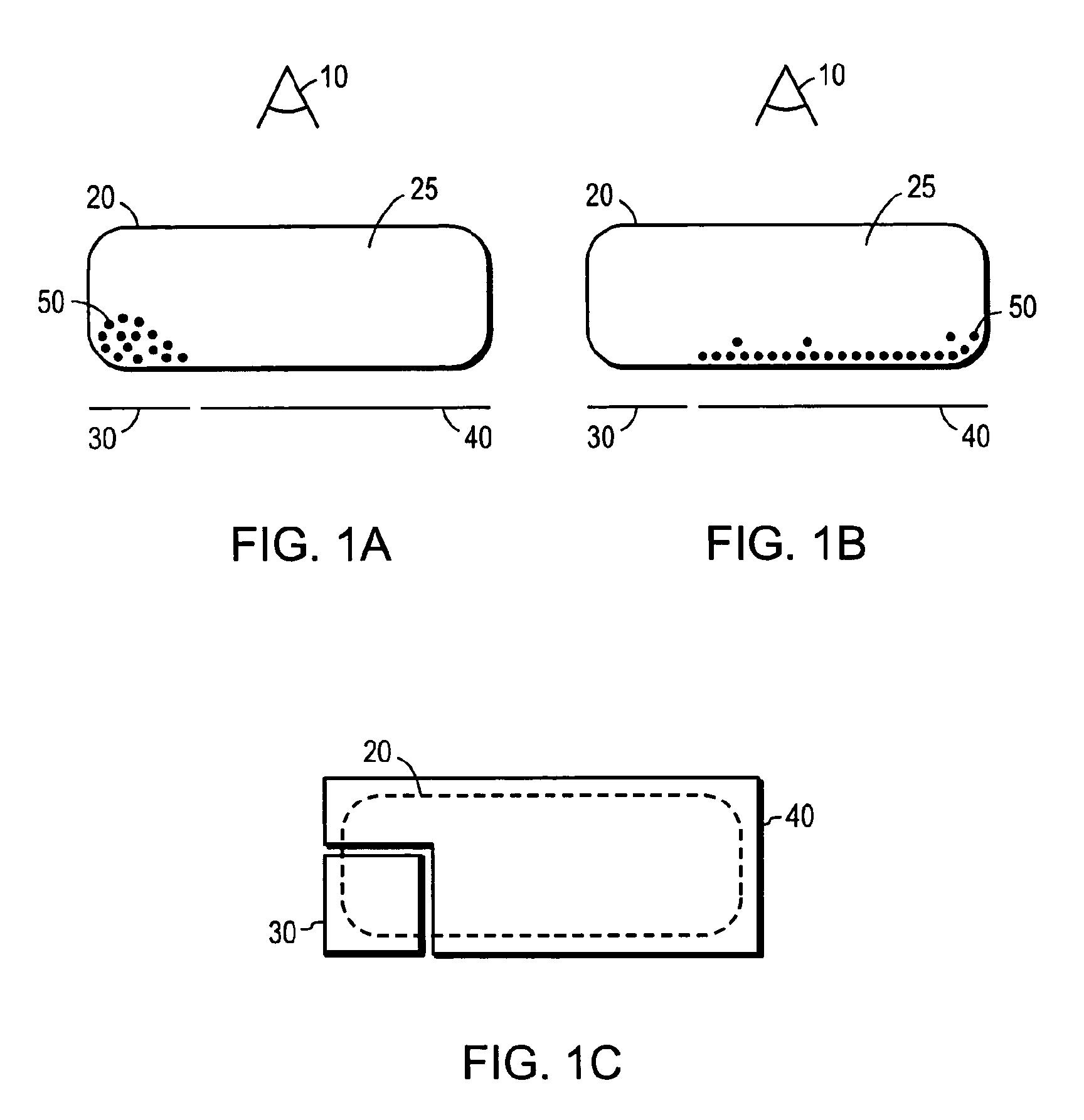
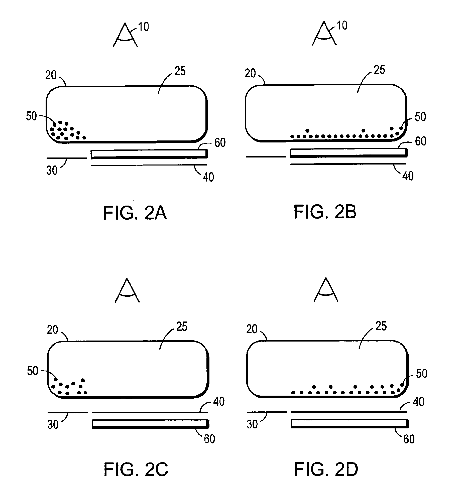
[0033]In yet another aspect, the present invention relates to an electrostatically addressable display comprising a substrate, an encapsulated electrophoretic display adjacent the substrate, and an optional dielectric sheet adjacent the electrophoretic display. Application of an electrostatic charge to the dielectric sheet or display material modulates the appearance of the electrophoretic display.

Problems solved by technology

Nevertheless, problems with the long-term image quality of non-encapsulated electrophoretic displays have prevented their widespread usage.
For example, particles that make up electrophoretic displays tend to settle, resulting in inadequate service-life for these displays.
Unfortunately, each color can only be displayed by part of the display area.
This area sharing approach result in colors less bright than is desirable.
Apart from being complicated and potentially expensive, such a multi-layer display requires precise alignment of the various layers, and highly light transmissive electrodes (and transistors, in the case of an active matrix display).

Method used


Image

  • Multi-color electrophoretic displays
  • Multi-color electrophoretic displays
  • Multi-color electrophoretic displays

Examples


Embodiment Construction

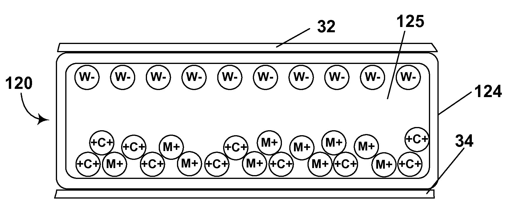
[0077]An electronic ink is an optoelectronically active material which comprises at least two phases: an electrophoretic contrast media phase and a coating / binding phase. The electrophoretic phase comprises, in some embodiments, a single species of electrophoretic particles dispersed in a clear or dyed medium, or more than one species of electrophoretic particles having distinct physical and electrical characteristics dispersed in a clear or dyed medium. In some embodiments the electrophoretic phase is encapsulated, that is, there is a capsule wall phase between the two phases. The coating / binding phase includes, in one embodiment, a polymer matrix that surrounds the electrophoretic phase. In this embodiment, the polymer in the polymeric binder is capable of being dried, crosslinked, or otherwise cured as in traditional inks, and therefore a printing process can be used to deposit the electronic ink onto a substrate. An electronic ink is capable of being printed by several different...


PUM

PropertyMeasurementUnit
diametersaaaaaaaaaa
dielectric constantaaaaaaaaaa
specific gravityaaaaaaaaaa

Abstract

A multi-color electrophoretic medium contains first, second and third species of particles, the particles having substantially non-overlapping electrophoretic mobilities and bring of three different colors. The particles are dispersed in a fluid having a fourth color. A method for driving such a display is also described.

Description

REFERENCE TO RELATED APPLICATIONS[0001]This application is a continuation-in-part of copending application Ser. No. 12 / 117,974, filed May 9, 2008 (Publication No. 2009 / 0040594), which is a continuation of copending application Ser. No. 11 / 970,811, filed Jan. 8, 2008 (Publication No. 2008 / 0150888), which is a continuation of application Ser. No. 10 / 729,044, filed Dec. 5, 2003 (now U.S. Pat. No. 7,352,353, issued Apr. 1, 2008), which is a continuation of application Ser. No. 09 / 140,860, filed Aug. 27, 1998 (now U.S. Pat. No. 6,710,540, issued Mar. 23, 2004). The aforementioned application Ser. No. 09 / 140,860 also claims priority to U.S. Ser. No. 60 / 057,133 filed Aug. 28, 1997, U.S. Ser. No. 60 / 057,716, filed Aug. 28, 1997, U.S. Ser. No. 60 / 057,122, filed Aug. 28, 1997, U.S. Ser. No. 60 / 057,798, filed Aug. 28, 1997, U.S. Ser. No. 60 / 057,799 filed Aug. 28, 1997, U.S. Ser. No. 60 / 057,163 filed Aug. 28, 1997, U.S. Ser. No. 60 / 057,118, filed Aug. 28, 1997, U.S. Ser. No. 60 / 059,358, filed S...

Claims


Application Information

Patent Timeline
Patent Type & Authority Applications(United States)
IPC IPC(8): G02F1/167
CPCG02F1/167G09G3/344G09G3/2003G02F2001/1678G02F1/1685G02F2203/02G02F1/13306
Inventor PAOLINI, JR., RICHARD J.HARRIS, GEORGE G.ALBERT, JONATHAN D.COMISKEY, BARRETT
Owner E INK CORPORATION
Learn More