
System for transmitting interacting data between neighboring bss via ms and method thereof

a technology of interacting data and transmitting system, applied in the field of wireless communication, can solve the problems of total latency, encapsulation/encapsulation delay, and unpredictable transmission latency

Inactive Publication Date: 2011-01-13
ALCATEL LUCENT SAS
View PDF8 Cites 14 Cited by
  • Summary
  • Abstract
  • Description
  • Claims
  • Application Information

AI Technical Summary

Benefits of technology

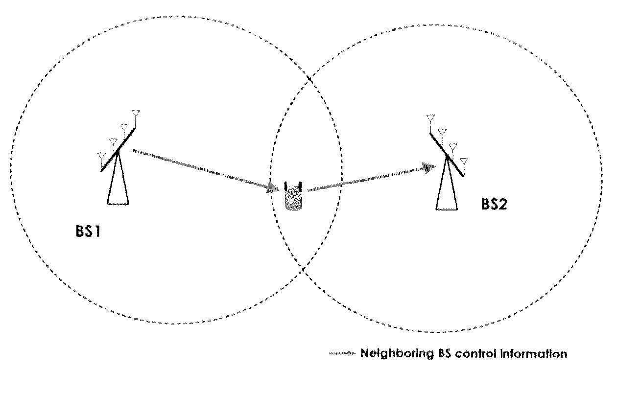
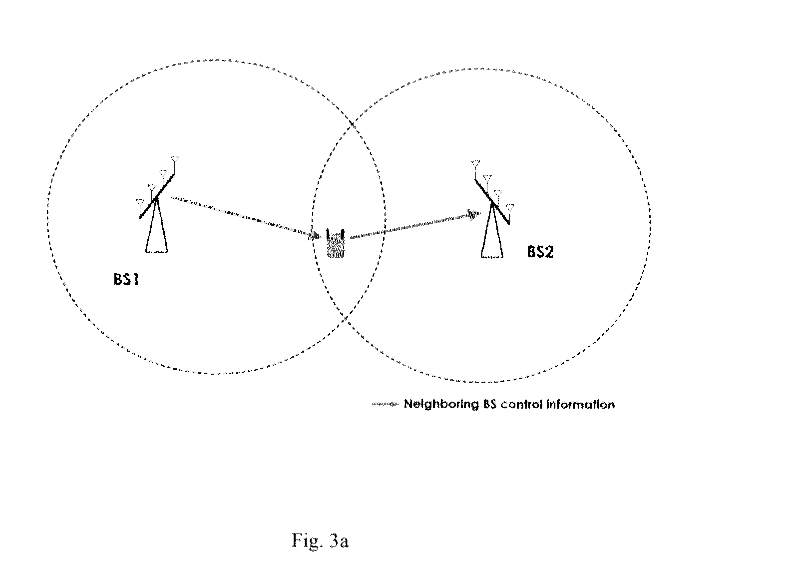
The present invention provides a system and method for transmitting interacting data between neighboring base stations (BSs) via a mobile device (MS). This solution reduces latency and predictability in controlling information exchange between BSs, which is important for efficient communication. The invention allows for direct communication between BSs using a MS, which simplifies data transmission and reduces latency. The system includes a first BS that transmits the interacting data to the MS, and the MS that receives and transmits the data to a second BS that neighbors the first BS. The invention also provides a communication system and method where the MS communicates with both BSs simultaneously using separate communication channels. Overall, the invention improves the efficiency and reliability of data transmission between neighboring BSs.

Problems solved by technology

The transmission latency is thus unpredictable.
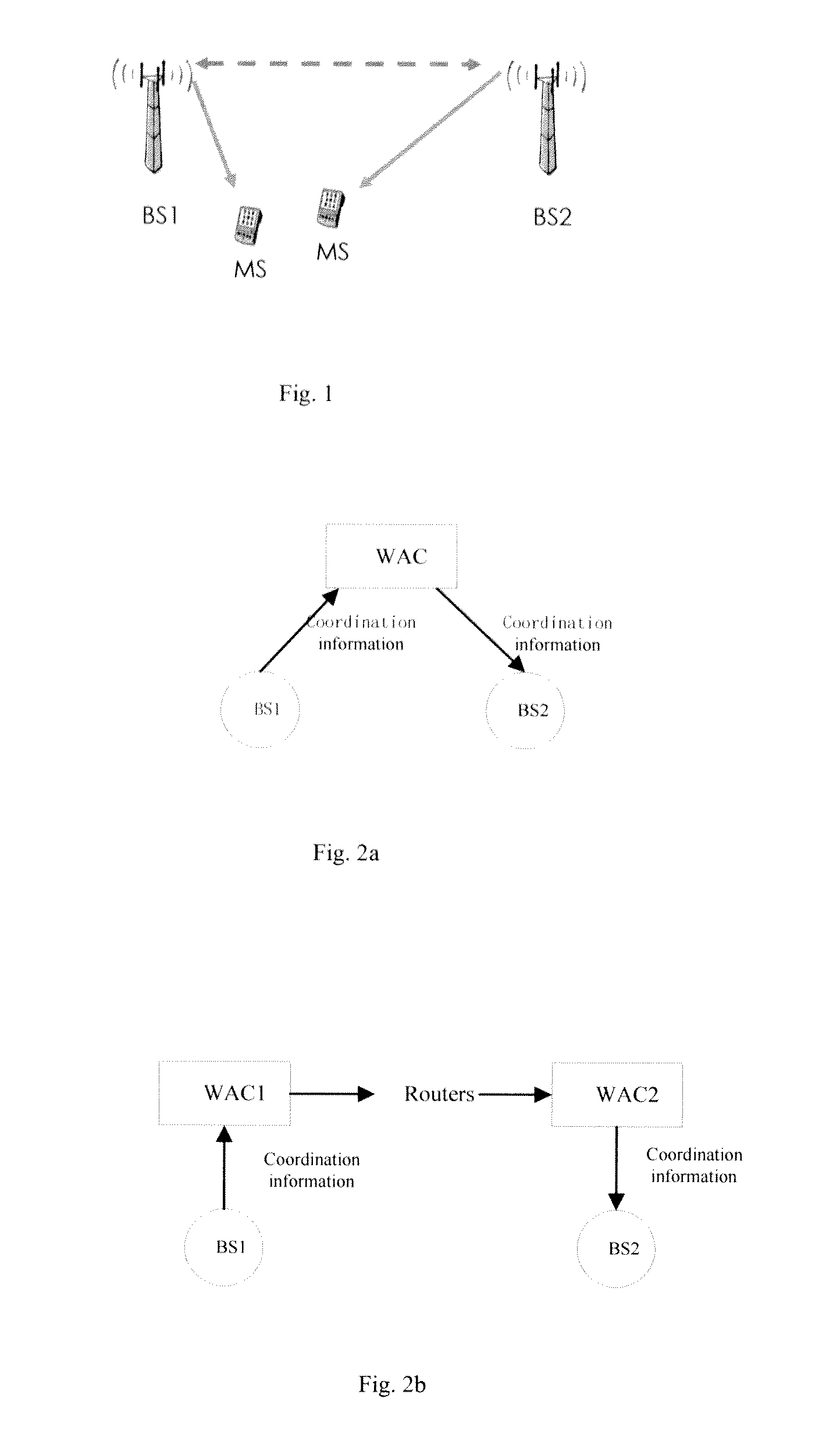
As can be seen from this procedure, the total latency may include transmitting delay, routing / switching delay, and possibly encapsulation / encapsulation delay.
Consequently, the total latency for control information transmission is unpredictable.
In summary, the latency for control information exchange between neighboring BS via a backbone is unpredictable, depending on neighboring BSs' locations and on which cluster they belong to.

Method used


Image

  • System for transmitting interacting data between neighboring bss via ms and method thereof
  • System for transmitting interacting data between neighboring bss via ms and method thereof
  • System for transmitting interacting data between neighboring bss via ms and method thereof

Examples


Embodiment Construction

[0030]Hereinafter, preferred embodiments of the present invention will be described with reference to the accompanying drawings, throughout which like components are denoted with like symbols or numbers. In the following description of the present invention, a detailed description of known functions and configurations incorporated herein will be omitted, otherwise it may obscure the subject matter of the present invention.

[0031]The total latency for control information transmission is not predictable due to the conventional wired transmission of the control information between the neighboring BSs. Therefore, there may be a long latency. This is unacceptable to communications which require less latency.

[0032]This invention provides a scheme of BS-BS data transmission via a MS. That is, interacting data between neighboring BSs is transmitted via a MS. The interacting data comprises data to be transmitted between neighboring BSs, such as user data (for example, data to be transmitted t...


PUM


Abstract

The present invention provides a system for transmitting interacting data between neighboring BSs via a MS and a method thereof The system comprises a first BS which transmits the interacting data to the MS, and a MS which receives the interacting data from the first BS and transmits the received interacting data to a second BS that neighbors to the first BS. The invention also provides a communication system and a method thereof, wherein a MS communicates with a first BS using an established first communication channel, and the MS to communicates with the second BS using an established second communication channel. The system of the invention uses a MS within the overlapped coverage area of neighboring BSs to perform transmission of interacting data such as control information for coordination, so as to reduce latency required for interacting data transmission between neighboring BSs. Compared to legacy BS coordination via a backbone, the BS coordination via a MS of the invention is predictable and requires less latency.

Description

BACKGROUND OF THE INVENTION[0001]1. Field of the Invention[0002]The present invention relates to the field of wireless communications, and in particular to a system for transmitting interacting data between neighboring BSs (Base Stations) via a MS (Mobile Station) and a method thereof. This invention also relates to a communication system and a method thereof.[0003]2. Description of the Prior Art[0004]IMT-Advanced next generation mobile networks have raised requirements on system capability. Some standard groups or organizations are actively developing drafts to meet the requirements, and expecting their drafts to be candidates for consideration in the IMT-Advanced evaluation process. IEEE802.16m task group which was recently launched aims to make some amendment to IEEE Std 802.16, in order to provide an advanced air interface with performance improvements for operation in licensed bands. It targets the cellular layer requirements of IMT-Advanced next generation mobile networks.[000...

Claims


Application Information

Patent Timeline
Patent Type & Authority Applications(United States)
IPC IPC(8): H04W4/00
CPCH04W92/20H04L5/0053H04W36/0005H04W36/22H04W72/04
Inventor SHEN, GANGNI, WEIWANG, DONGYAOJIN, SHAN
Owner ALCATEL LUCENT SAS
Learn More