
Rotor blade for a wind turbine and method for its production

a technology of wind turbine and rotor blade, which is applied in the direction of propellers, propulsive elements, water-acting propulsive elements, etc., can solve the problems of inability to accurately measure the inner contour of the half shell, the deviation of positioning in the shear web, and the difficulty of installation of the shear web, etc., to achieve high strength, increase the strength of the glue bond, and the effect of durable glue bond

Inactive Publication Date: 2011-01-13
NORDEX ENERGY
View PDF7 Cites 53 Cited by
  • Summary
  • Abstract
  • Description
  • Claims
  • Application Information

AI Technical Summary

Benefits of technology

[0013]The glue bond of the first surface of the connecting profile with one of the girders and the glue bonding of the second surface of the connecting profile with a first lateral surface of the at least one shear web is preferably a large-area glue bond with a contact surface which is larger than one of the front surfaces of the at least one shear web. This promotes a stable glue bond.
[0034]In accordance with one embodiment of the method, the collet of the connecting profile is filled with glue up to a predetermined level before inserting the at least one shear web. Basically, the glue can also be applied to the contact surfaces of the at least one shear web to be glued. However, a controlled filling of the collet facilitates the application of the correct amount of glue. By inserting the at least one shear web into the collet at least partially filled with glue, an even distribution of the glue and a good coating of all contact surfaces of the at least one shear web and the connecting profile to be glued are also achieved. Optionally, after filling the collet with glue, the glue arrangement can be secured with a position locking device for preventing dripping or leaking of the glue from the collet. This position locking device, for example a lamellar material, can then be removed immediately before inserting the shear web into the collet.

Problems solved by technology

However, the installation of the shear webs is difficult.
However, because of the inner contour of the half shell not always being dimensionally stable or of the contact surface of the girder adjacent to the fastening section of the shear web, positioning deviations in the shear web can easily occur.
The inaccuracies in the inner contour of the half shells result from the production of the half shells in open molds.
The glue bond is also called a blind glue bond, because after fitting the second half shell large areas are no longer accessible and the quality cannot be checked or is hard to check.
Due to the mentioned tolerances of the inner contours of the half shells and the inaccuracies during the positioning of the shear webs, complex refinishing may be required: If the required inner width between the half shells is fallen short of, the shear webs can lock and make an exact arranging of the two half shells impossible.

Method used


Image

  • Rotor blade for a wind turbine and method for its production
  • Rotor blade for a wind turbine and method for its production
  • Rotor blade for a wind turbine and method for its production

Examples


Embodiment Construction

[0040]While this invention may be embodied in many different forms, there are described in detail herein a specific preferred embodiment of the invention. This description is an exemplification of the principles of the invention and is not intended to limit the invention to the particular embodiment illustrated

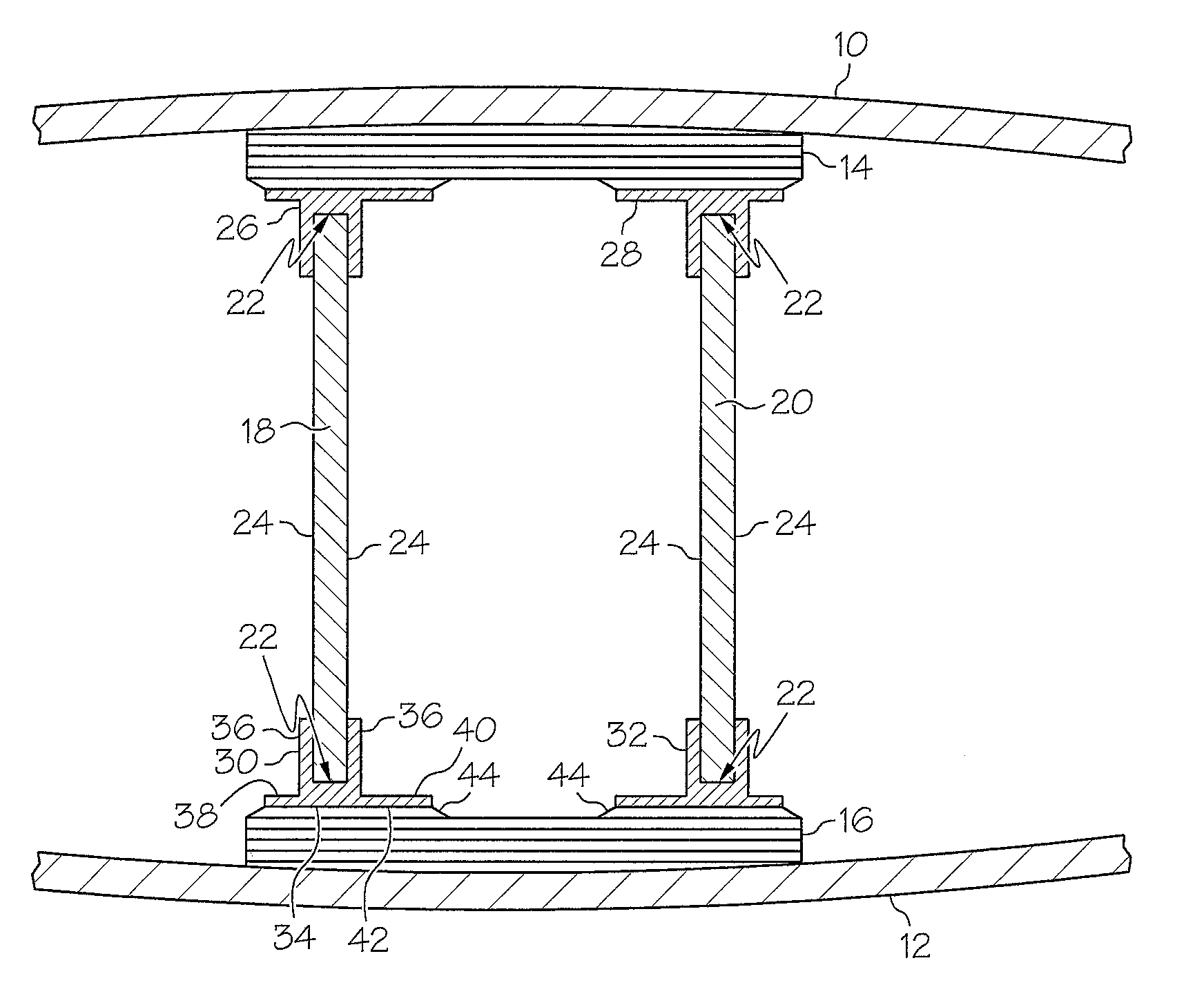
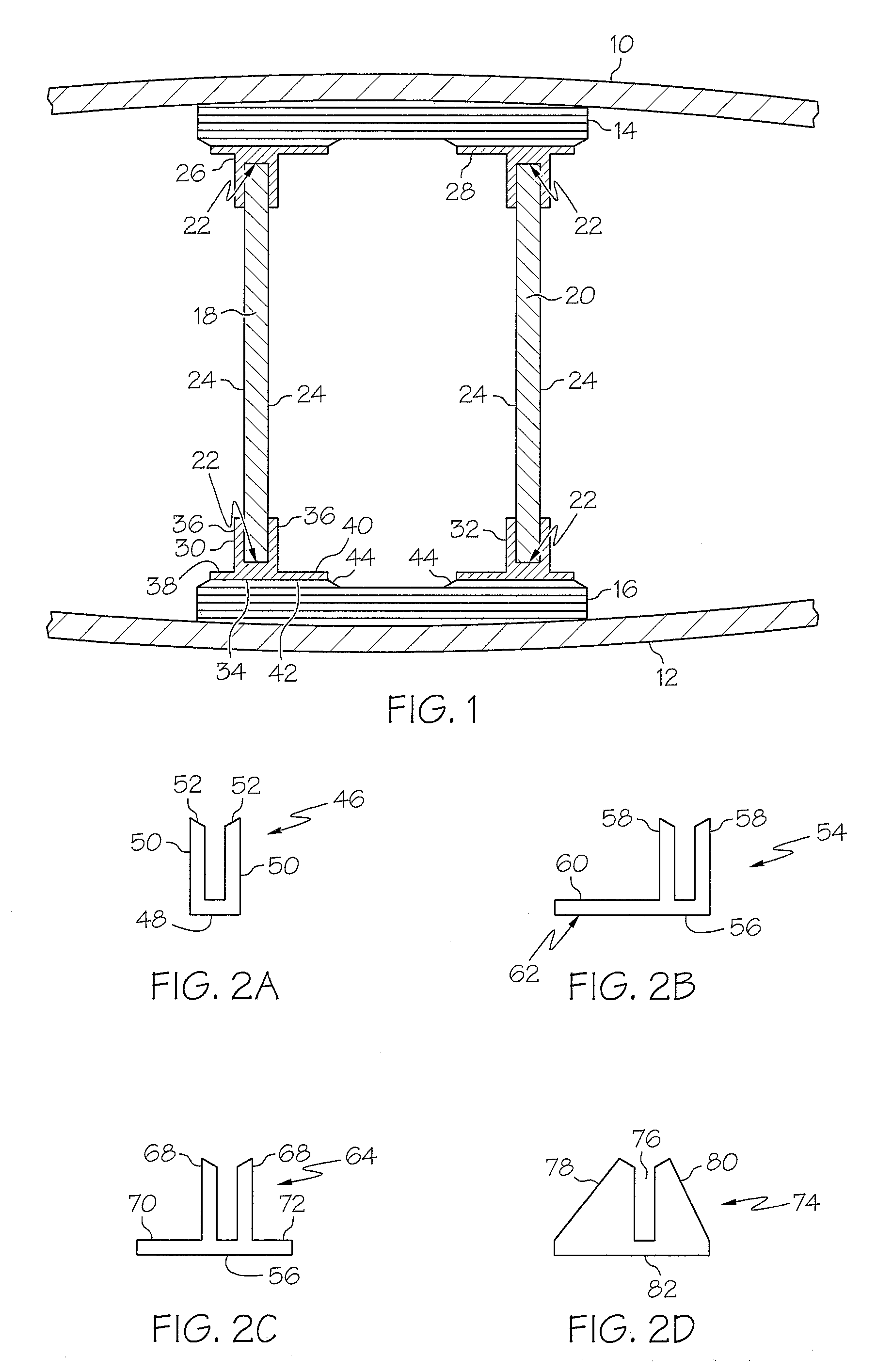
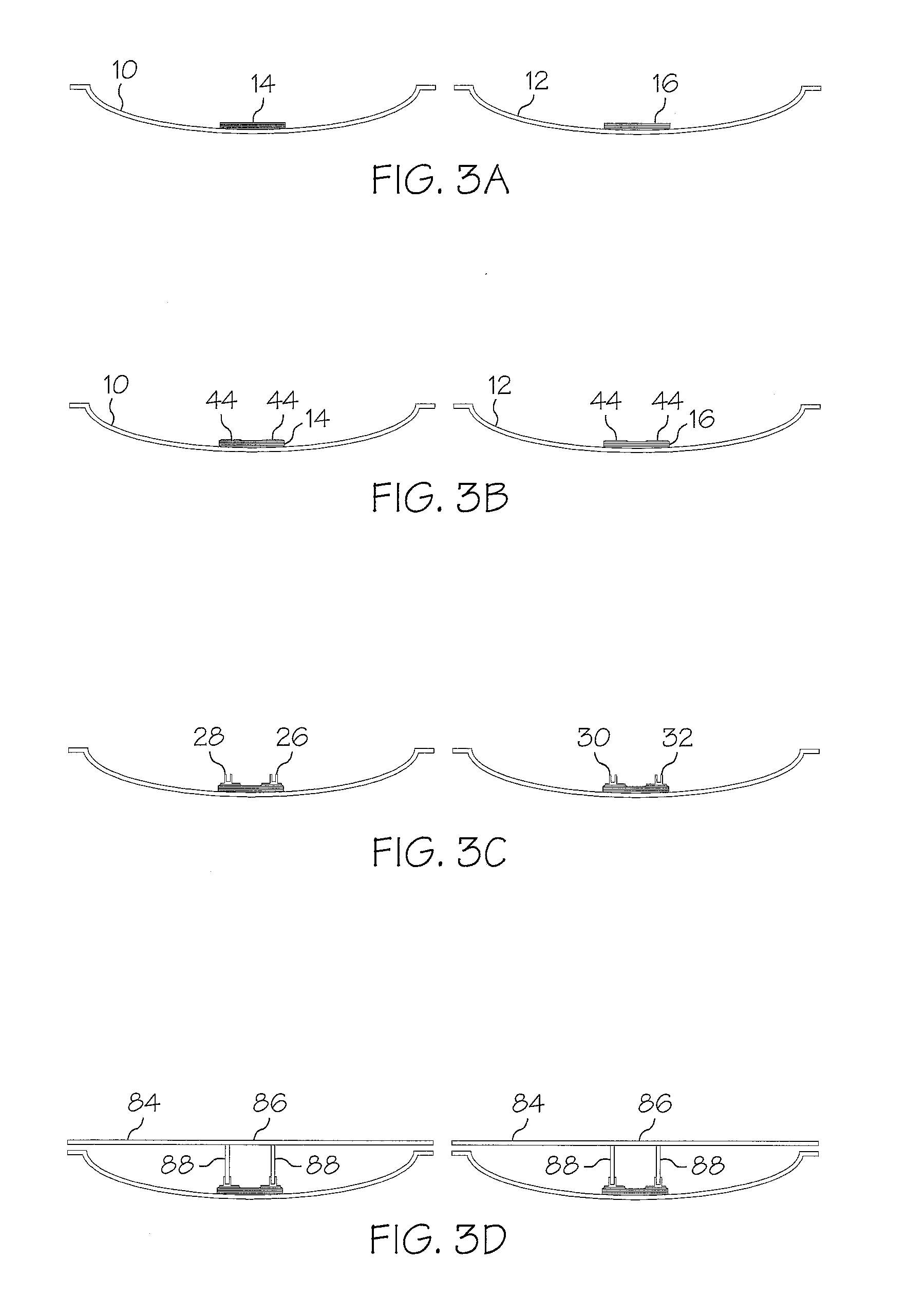
[0041]FIG. 1 shows a detail of a cross-section through a rotor blade according to the invention. The upper half shell 10 which forms the aerodynamic casing of the rotor blade, is indicated in the upper part of the figure. Accordingly, the bottom half shell 12 of the rotor blade is located in the bottom part of the figure. A girder 14 of the rotor blade is permanently joined to the first half shell 10 and a girder 16 of the rotor blade to the second half shell 12. The two girders 14, 16 each consist of a plurality of glass plies which are e.g. saturated with a polyester or epoxy resin and thus form to a laminate. The girders 14, 16 are arranged in the area of the largest profil...


PUM

PropertyMeasurementUnit
angleaaaaaaaaaa
angleaaaaaaaaaa
areaaaaaaaaaaa

Abstract

A rotor blade for a wind turbine comprising at least one pair of girders lying opposite each other which extend in the longitudinal direction of the rotor blade and carry forces acting on the rotor blade, and at least one shear web which has two front surfaces, each of which is facing one of the two girders, and two lateral surfaces, wherein that shear web extends between the two girders in the longitudinal direction of the rotor blade and is permanently joined to the two girders, wherein at least one connecting profile having a single- or multi-piece cross-section is running in the longitudinal direction of the rotor blade and comprises a collet, into which the at least one shear web is inserted, wherein a first surface of the connecting profile is glued to one of the girders and a second surface of the connecting profile is glued to a lateral surface of the at least one shear web.

Description

CROSS-REFERENCE TO RELATED APPLICATIONS[0001]Not applicable.STATEMENT REGARDING FEDERALLY SPONSORED RESEARCH[0002]Not applicable.BACKGROUND OF THE INVENTION[0003]The invention relates to a rotor blade for a wind turbine which has at least one pair of girders lying opposite each other which extend in the longitudinal direction of the rotor blade and carry forces acting on the rotor blade, and at least one shear web which has two front surfaces, each is facing one of the two girders, and two lateral surfaces, wherein that share web extends between the two girders in the longitudinal direction of the rotor blade and is permanently joined to the two girders, and a method for the production of such rotor blades.[0004]Known rotor blades of this design consist of two half shells that are joined to each other. Each half shell has one of the girders usually in the area of the largest profile height. The girders can be produced integrally with the half shells and, among other things, give the...

Claims


Application Information

Patent Timeline
Patent Type & Authority Applications(United States)
IPC IPC(8): B64C11/24B21K3/04
CPCF03D1/0675Y02E10/721B29C65/5071B29C65/5085B29C66/112B29C66/114Y10T29/49339B29C66/43441B29C66/532B29C66/54B29C66/61B29C66/721B29L2031/085B29C66/4326B29C66/636B29C66/71B29C66/7212Y02E10/72Y02P70/50B29K2309/08B29K2067/00B29K2063/00
Inventor GAU, LUTZ-REINER
Owner NORDEX ENERGY
Learn More