High-pressure compression unit for process fluids for industrial plant and a related method of operation

a technology of process fluids and industrial plants, applied in mechanical equipment, non-positive displacement pumps, liquid fuel engines, etc., can solve the problems of reduced compression process efficiency, difficulty in disposing, and reduced efficiency of the compression process itsel

Active Publication Date: 2011-01-13
NUOVO PIGNONE TECH SRL
View PDF5 Cites 19 Cited by
  • Summary
  • Abstract
  • Description
  • Claims
  • Application Information

AI Technical Summary

Benefits of technology

[0023]The general aim of the present invention is to produce a high-pressure compression unit for use in industrial plant, which is able to overcome, at least partially, the above-mentioned problems present in the known technology.

Problems solved by technology

Hydrocarbons are present in nature in various forms and in mixtures with other gases, which are of little interest and which are difficult to dispose of.
In order to compress the fluid, without condensates, it is possible to compress it by limiting or eliminating inter-refrigeration, with a consequent reduction in the efficiency of the compression process itself.
One disadvantage of the traditional high-pressure compression units is the fact that they are technically difficult to design because of the various problems of a mechanical or fluid-dynamic nature that are encountered on increasing the maximum output pressure.
Examples of such technical difficulties are: the complications of the systems of external sealing, the fluid dynamic performance and others.
Another disadvantage is that the compression units are increasingly required to operate at pressures well above the critical pressure of the process fluid, causing a worsening of the above-mentioned technical problems.
In addition, the compression of a super-critical fluid at high temperature reduces the efficiency of the compressor.
A further disadvantage is that in the event that a normal pump is used externally to the compression unit, even though such use may contribute to a significant increase in the cost of the plant, there is a high risk that losses of gas into the atmosphere will arise, which is particularly critical if acid gases are present.
In fact, the use of a pump mechanically connected to the compression unit by means of a shaft passing to the outside, although in some cases this may reduce the mechanical complexity of the machine (it is possible to use a single motor to drive the compressor and the pump), it does bring a significant risk of gas losses from the external dynamic seals that must be fitted on the shaft connecting the unit and the pump.
These external dynamic seals are therefore particularly critical in the presence of acid fluids, which increases the cost of design and maintenance of the unit in order to guarantee the necessary safety.
A further disadvantage is the fact that traditional machines are bulky and heavy and therefore relatively expensive to transport and install, particularly in marine or submarine applications where weight is important, such as for example in platforms, “Floating Storage and Offloading units” (units operating at anchor in the open sea for the storage of oil after extraction from a marine field), submarine wells and other cases.

Method used


Image

  • High-pressure compression unit for process fluids for industrial plant and a related method of operation
  • High-pressure compression unit for process fluids for industrial plant and a related method of operation
  • High-pressure compression unit for process fluids for industrial plant and a related method of operation

Examples


first embodiment

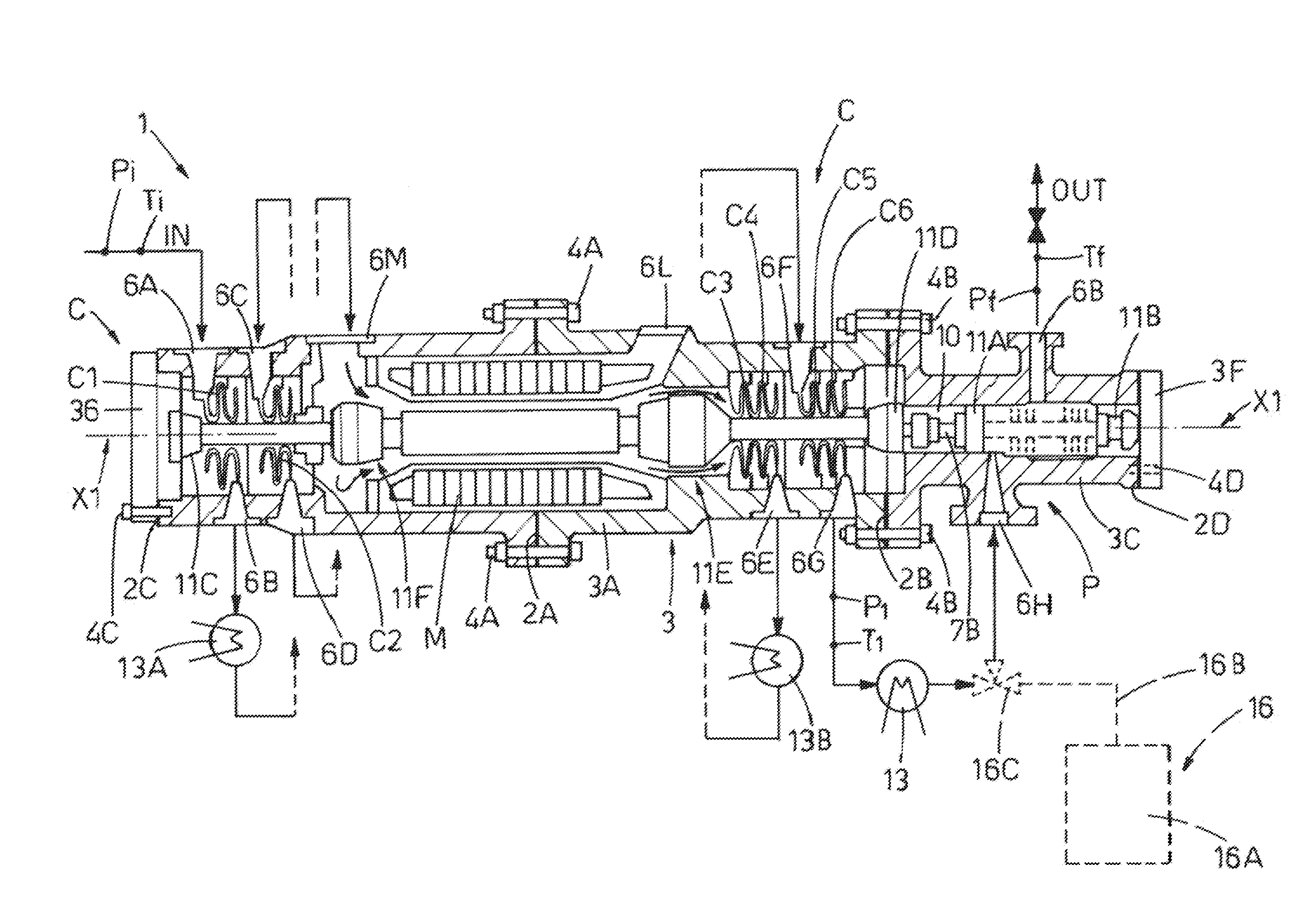
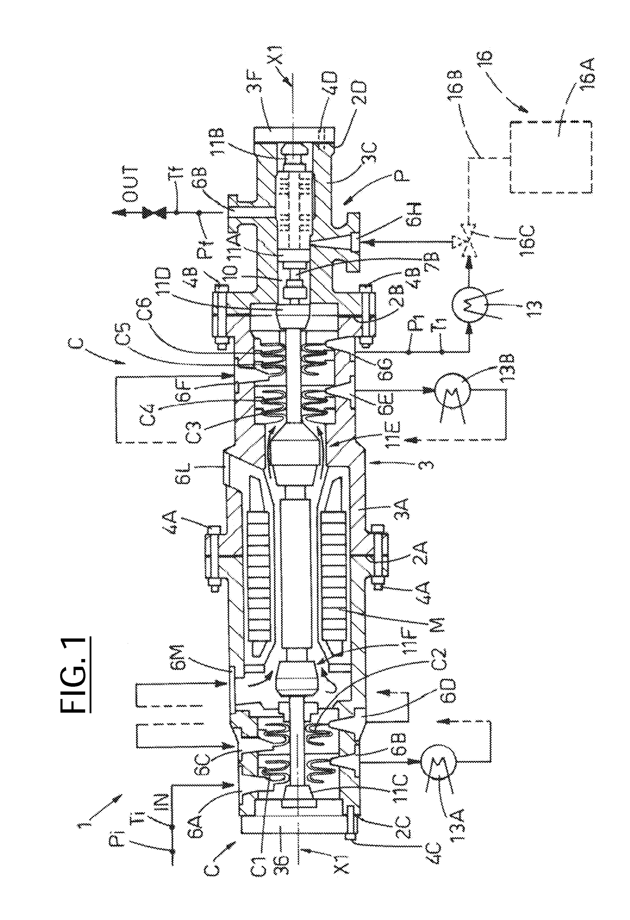
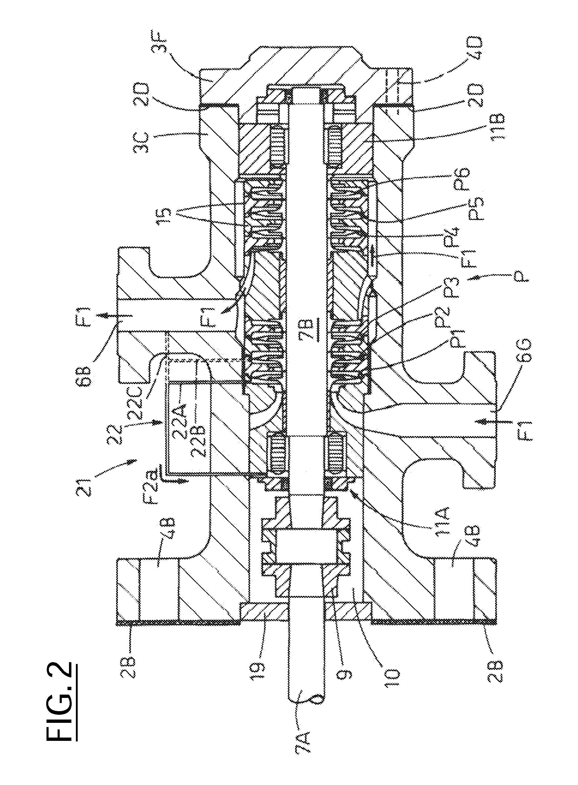
[0125]In a first embodiment, the cooling system, 21 comprises at least one first fluid dynamic circuit 22 produced using ducts 22A, 22B or 22C—still referring to FIG. 2—able to tap off, see arrow F2a, a part of the process fluid from the first stage P1, from an intermediate stage P2-P6 or respectively from the outlet aperture 6B of the pump P.

second embodiment

[0126]The pressure of the fluid tapped off is however higher and the temperature is lower in comparison with those of the output of the compressor C; in this manner the fluid can cool the bearing 11A and penetrate the aperture 10, from which it can leave via the first seal 19 in the form of leakage or loss from the said seal, reintroducing itself into the output of the compressor C. In a second embodiment, the cooling system 21 comprises at least one second fluid-dynamic circuit 23—see FIG. 3—produced with first ducts 23A able to tap off, see arrow F2b, part of the process fluid from intake 6G of the pump P, and mounted on support 15B of bearing 11A and / or through second ducts 23B mounted between the support 15B and the rotor 7B.

[0127]A first or second relief pipe 23D, 23E is advantageously provided in order to provide a fluid link, still referring to arrow F2b, between the bearing 11A and one of the stages C1 to C6 of the compressor C or respectively in order to provide a fluid lin...

third embodiment

[0129]In a third embodiment, the cooling system 21 comprises at least a third fluid dynamic circuit 24—see FIG. 4—able to cool bearing 11A thanks to part of the process fluid coming, see arrow F2c, from the output of compressor C via a calibrated tapping from the first seal 19 or, as an alternative, from a hole into the passage aperture 10, that is, eliminating seal 19.

[0130]In addition, provision is made for suitable pipes 24A on the support 15B for the bearing 11A and / or a space 24B produced around the rotor 7B in order to provide a fluid link, still referring to arrow F2c, between the bearing 11A and the first stage P1 of the pump P, in such a manner that the cooling fluid can mix with the process fluid upstream of the pump P.

[0131]In combination with this third fluid dynamic circuit 24 provision can also be made for cooling devices (not shown in the diagram for simplicity) between the compressor C and the pump P, or better in the passage aperture 10, so as to permit the cooling,...


PUM


Abstract

An integrated high-pressure compression unit for a process fluid that includes at least a first compression device able to compress the process fluid from a essentially gaseous initial thermodynamic state to an intermediate thermodynamic state, a second compression device connected mechanically to the first compression device and able to compress the process fluid from the intermediate thermodynamic state to a final thermodynamic state, a motor device able to drive the first compression device and the second compression device, and a pressure casing or housing in which at least the said first and second compression devices are mechanically coupled to each other.

Description

CROSS-REFERENCE TO RELATED APPLICATIONS[0001]This application claims priority under 35 U.S.C. §119(a)-(d) or (f) to prior-filed, co-pending Italian patent application number MI2009A001235, filed on Jul. 10, 2009, which is hereby incorporated by reference in its entirety.STATEMENT REGARDING FEDERALLY SPONSORED RESEARCH OR DEVELOPMENT[0002]Not applicable.NAMES OF PARTIES TO A JOINT RESEARCH AGREEMENT[0003]Not applicable.REFERENCE TO A SEQUENCE LISTING, A TABLE, OR COMPUTER PROGRAM LISTING APPENDIX SUBMITTED ON COMPACT DISC[0004]Not applicable.BACKGROUND OF THE INVENTION[0005]1. Field of the Invention[0006]The present invention refers to a high-pressure compression unit, preferably but not exclusively for use in re-injection plant for gases, whether acid or not, and a related method for compressing a process fluid.[0007]2. Description of Related Art[0008]A compressor is a machine capable of increasing the pressure of a compressible fluid (gas) through the use of mechanical energy. The ...

Claims


Application Information

Patent Timeline
Patent Type & Authority Applications(United States)
IPC IPC(8): F04D1/06F04D17/12F04D29/58F04D29/42
CPCF04D17/122F04D29/584F04D29/286F04D19/02F04D29/059F04D25/0686F04D31/00F04D1/06F04D7/02F04D13/06F04D17/12
Inventor PALOMBA, SERGIOMASI, ANDREADE IACO, MARCOCAMATTI, MASSIMOBERGAMINI, LORENZO
Owner NUOVO PIGNONE TECH SRL
Why Eureka
Try Eureka