
Hand tool

a technology of hand tools and levers, which is applied in the direction of metal-working holders, supports, positioning apparatuses, etc., can solve the problems of difficult actuation of short release levers of shaft release mechanisms, used for one caliper unit types,

Active Publication Date: 2011-01-20
PRIVATE BRAND TOOLS AUSTRALIA
View PDF10 Cites 22 Cited by
  • Summary
  • Abstract
  • Description
  • Claims
  • Application Information

AI Technical Summary

Benefits of technology

[0024]The forward region at the lower end of the lever can be shaped for easy gripping by the user. Whilst using a thumb to grip the handle, an index finger of the user can be locatable within a groove whereas the three remaining fingers of the user can be locatable within an arcuate recess located immediately below the groove.
[0031]The shaft assembly can comprise a handle mounted to the shaft to help the user pull the shaft in the reverse direction. The handle can also serve as a travel stop (by colliding with the body), to determine how far a load applying member may move relative to the body.
[0035]The shaft release mechanism can allow for disengagement of the load applying members from the first and second surfaces when the shaft is moved in the reverse direction, even if the tool is under heavy load.
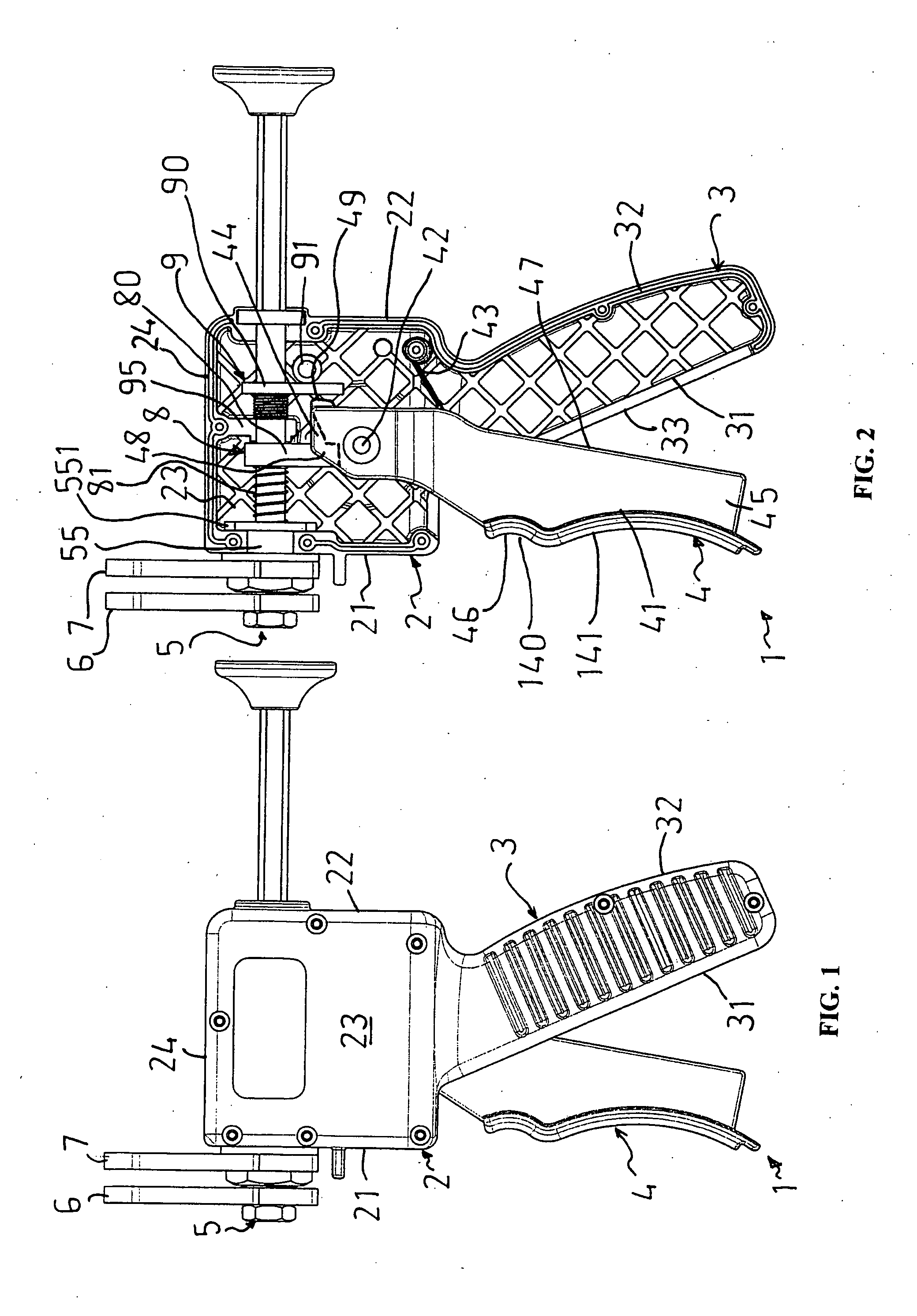
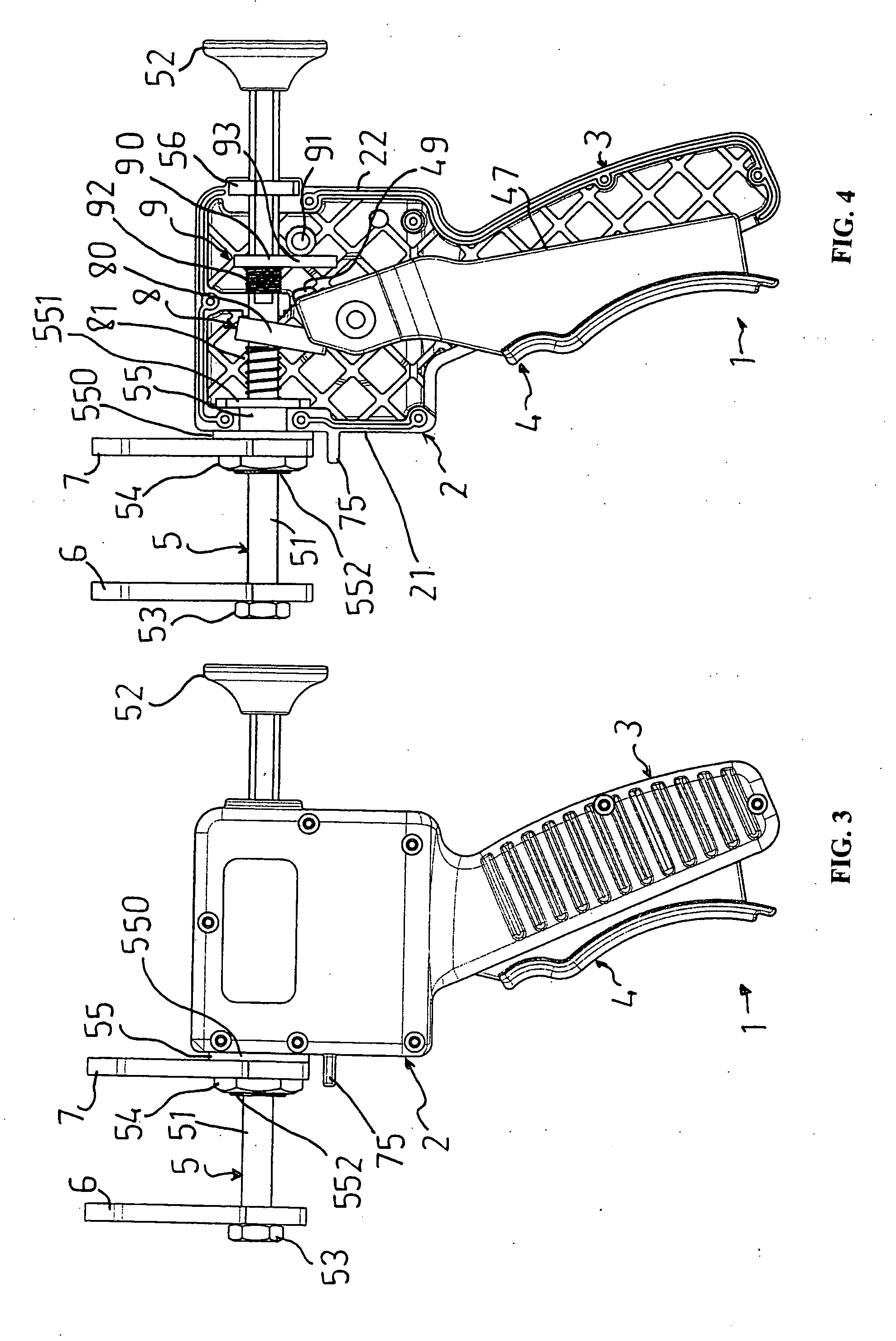
[0041]The shaft locking member can be moved between the locking position and the unlocking position by the lever, whereby the mid-region rocks / pivots on the pivot point to correctly orientate the shaft relative to the aperture of the shaft locking member. When wishing to release the shaft, the lower end of the shaft locking member can be moved in a rearward direction by the lever to the unlocking position, at which time the mid-region rocks / pivots about the pivot point, and the shaft locking member releases the shaft, thereby allowing the shaft to be freely moved by hand through the shaft locking member aperture in the reverse direction. Preferably, the locking member is in the form of an oblong plate or bar being of sufficient width so as to adequately grip / bite the shaft. A region of the shaft extending through the locking member can be other than circular so as to provide a better gripping surface.
[0058]The forward region at the lower end of the lever can be shaped for easy gripping by the user. Whilst using a thumb to grip the handle, an index finger of the user can be locatable within a groove whereas the three remaining fingers of the user can be locatable within an arcuate recess located immediately below the groove.
[0075]The shaft locking member can be moved between a locking position and an unlocking position by the lever, whereby the mid-region rocks or pivots on the pivot point to correctly orientate the shaft relative to the aperture of the shaft locking member. When wishing to release the shaft, the lower end of the shaft locking member can be moved in a rearward direction by the lever to the unlocking position, at which time the mid-region rocks / pivots about the pivot point, and the shaft locking member releases the shaft, thereby allowing the shaft to be freely moved by hand through the shaft locking member aperture in the reverse direction. Preferably, the locking member is in the form of an oblong plate or bar being of sufficient width so as to adequately grip the shaft. A region of the shaft extending through the locking member can be other than circular so as to provide a better gripping surface.

Problems solved by technology

A disadvantage of each above mentioned tool is that it can only be used for the one caliper unit type that it was designed for.
Yet another disadvantage is that, when the tool is under heavy load, a short release lever of the shaft release mechanism can be difficult to actuate so as to allow the shaft to be moved in the reverse direction.

Method used


Image

  • Hand tool
  • Hand tool
  • Hand tool

Examples


Embodiment Construction

[0118]In the figures, like reference numerals refer to like features.

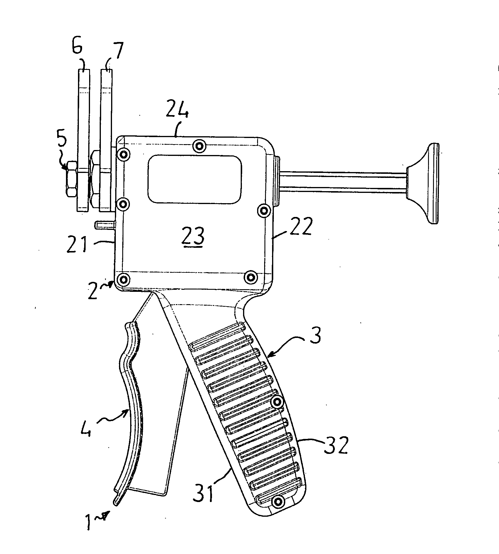
[0119]FIGS. 1-15 show a hand tool 1 for applying loads to first and second spaced apart surfaces, such as surfaces of a caliper unit of a vehicle disc-brake assembly. The tool 1 includes a body 2, a handle 3 extending from the body 2, a lever assembly 4, a shaft assembly 5, a movable load applying member 6, a fixed load applying member 7, a shaft drive mechanism 8 and a shaft release mechanism 9.

[0120]The body 2 has walls that provide a housing for various components of the tool. The housing 2 is in two detachable pieces (connected together with screws—not labelled) so as to allow ready access to components located within. As seen in FIGS. 1 and 2, the body 2 has a front wall 21, a rear wall 22, a pair of side walls 23 and a top wall 24. The body 2 is made of molded plastics material.

[0121]The handle 3 and body 2 are of unitary construction. The handle 3 is in the form of a pistol grip handle 3 extending from a low...


PUM

PropertyMeasurementUnit
Angleaaaaaaaaaa

Abstract

A hand tool (1) for compressing first and second spaced apart surfaces of a caliper unit of a vehicle disc-brake assembly. The tool (1) comprises: a body (2); a handle (3) extending from the body (2); a hand-operable lever (4) pivotally connected to the body (2) and pivotable from a resting position towards the handle (3) to a working position; a shaft (5) extending through the body (2) along a longitundal axis, and movable between forward and reverse directions along the axis relative to the body (2); a movable load applying plate (6) mounted to the shaft (5) for applying a compressive force to the first surface when moved by the shaft (5) in the forward direction into engagement with the first surface, wherein the movable load applying plate (6) is mounted to a forward end of the shaft (5) and is rotatable relative to the longitudinal axis through an angle of about 180°; a fixed load applying plate (7) held relative to the body (2) and not movable by the shaft (5), for applying a compressive force to the second surface when brought into engagement with the second surface, wherein the fixed load applying plate (7) is rotatable relative to the longitudinal axis through an angle of about 180°; a shaft drive mechanism (8) mounted to the body (2) and operatively connected to the shaft (5) and lever (4) such that pivoting of the lever (4) to the working position causes the shaft drive mechanism (8) to incrementally advance the shaft (5) only in the forward direction; and a shaft release mechanism (9) mounted to the body (2) and operatively connected to the shaft (5) and lever (4) such that movement of the lever (4) from the resting position away from the working position enables the shaft (5) to be moved in the reverse direction.

Description

FIELD OF THE INVENTION[0001]This invention relates to a hand tool of the type having a body, a hand-operable lever pivotably connected to the body, and a shaft extending through the body that is incrementally advanced in a forward direction relative to the body when actuating the lever. In a preferred embodiment, the invention concerns a hand tool having movable and fixed load applying members, for spreading vehicle brake pads of different types of disc-brake assemblies and for compressing caliper pistons of those assemblies.BACKGROUND OF THE INVENTION[0002]Over the life of a vehicle, worn brake pads of disc-brake assemblies will need to be replaced a number of times. This is usually accomplished by first spreading the worn brake pads, forcing each caliper piston into its piston housing, and then replacing the worn pads with new pads.[0003]Hand tools for spreading vehicle brake pads and for compressing caliper pistons are know. One such tool is described in the specification of U.S....

Claims


Application Information

Patent Timeline
IPC IPC(8): B25B27/00B23P19/04
CPCB25B27/0035F16D65/0043Y10T29/53891Y10T29/53683Y10T29/53909Y10T29/53896
Inventor MITCHELL, DAVID
Owner PRIVATE BRAND TOOLS AUSTRALIA
Learn More