Screen

a technology for screens and screens, applied in the field of screens, can solve the problems of easy deterioration of the quality of images projected on the screen roll, high flatness of the panel screen and the stretched screen, and inability to be compact in storage, so as to save space and facilitate formation

Active Publication Date: 2011-01-20
SEIKO EPSON CORP
View PDF4 Cites 22 Cited by
  • Summary
  • Abstract
  • Description
  • Claims
  • Application Information

AI Technical Summary

Benefits of technology

[0031]According to this structure, the respective substrates are properly combined by the combining unit when the substrates are drawn from the housing and formed into the screen base body. Thus, the screen base body can be appropriately and easily formed by combining the substrates accommodated in the housing.
[0032]Moreover, each of the substrates can be wound around the corresponding winding shaft. Thus, space saving of the housing can be achieved, and the screen as well as the housing can be made compact.

Problems solved by technology

In these examples, the panel screen and the stretched screen have high flatness but cannot be made compact in storage.
In this case, the quality of the images projected on the roll screen easily deteriorates.
Thus, handling of the screen becomes complicated.
In this case, however, the weight of the connecting parts increases and thus the entire screen becomes heavy when the screen base body has about 100 inches.

Method used


Image

  • Screen
  • Screen
  • Screen

Examples


first embodiment

Modifications of First Embodiment

[0079]FIG. 4 is a side view illustrating a screen 1A as a modified example of the screen 1.

[0080]The screen 1A which includes engaging portions having different shapes can offer advantages similar to those of the screen 1.

[0081]More specifically, the screen 1A has functions similar to those of the screen 1, and has structure similar to that of the screen 1 except for a screen base body 5A provided instead of the screen base body 5. As illustrated in FIG. 4, the screen base body 5A has structure similar to that of the screen base body 5 except for connecting parts 513 and 523 disposed on the surfaces 511B and 521B and having plural engaging portions 5131 and 5231 in place of the connecting parts 512 and 522.

[0082]The engaging portions 5131 and 5231 are bar-shaped members made of the same synthetic resin. Similarly to the engaging portions 5121 and 5221, the engaging portions 5131 and 5231 extend in the width directions of the surfaces 511B and 521B to...

second embodiment

2. Second Embodiment

[0096]A screen according to a second embodiment is now described.

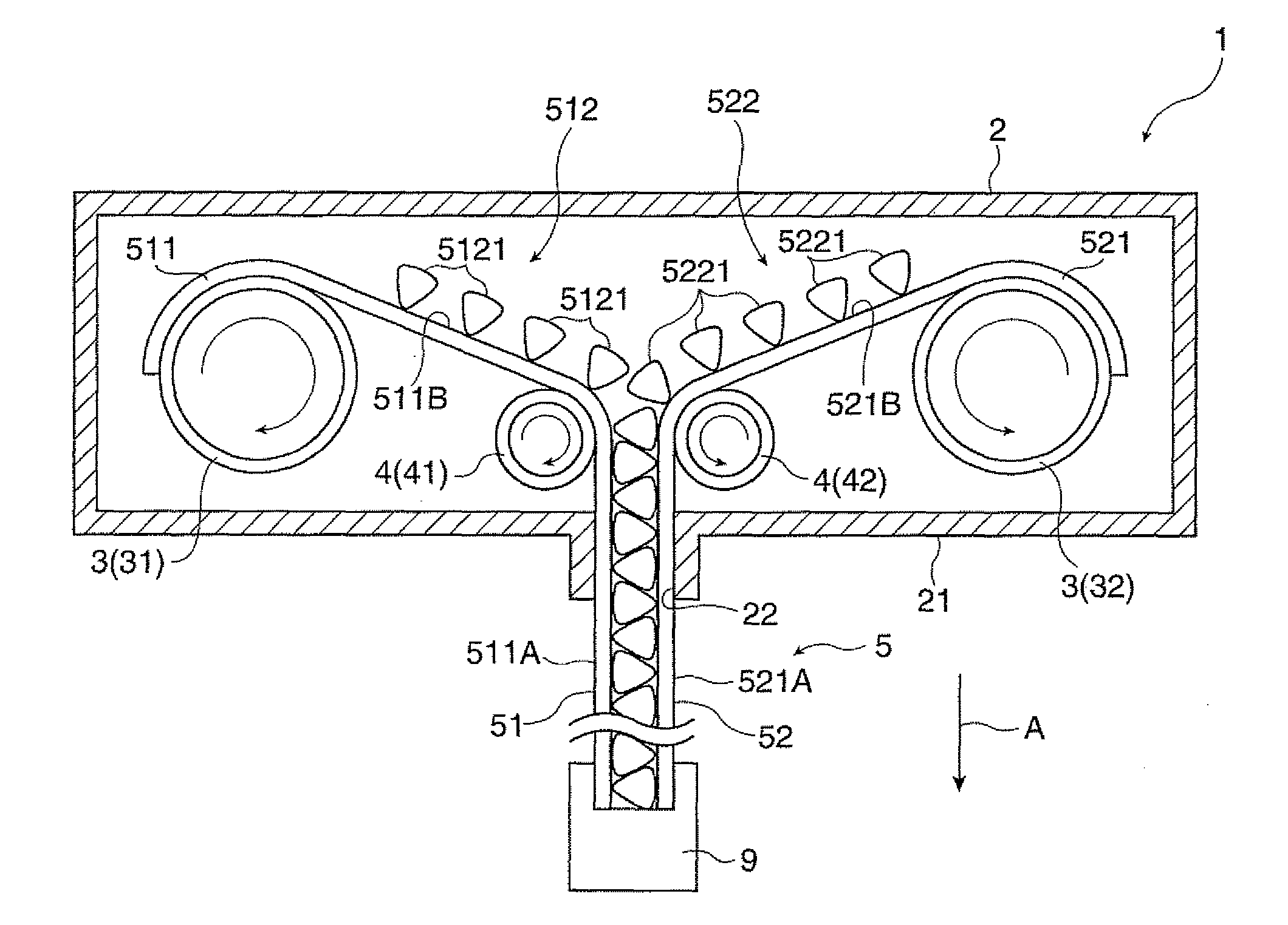
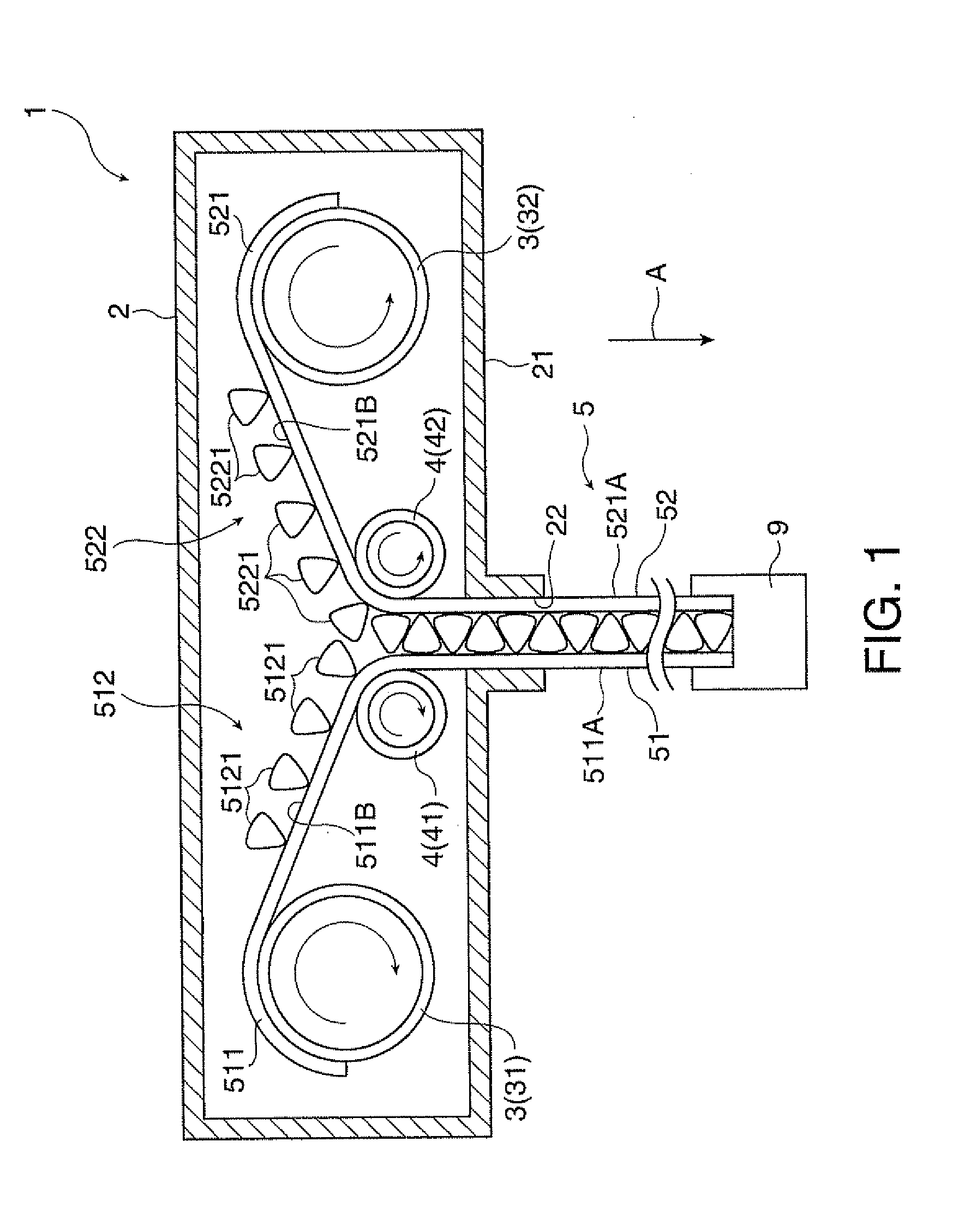
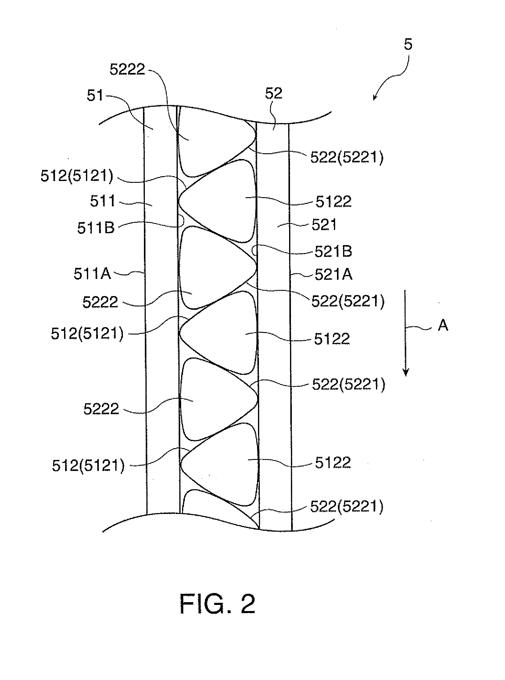
[0097]The screen in this embodiment has structure similar to that of the screen 1. According to the screen 1, the substrates 51 and 52 are combined by engagement between the connecting parts 512 and 522. According to the screen in this embodiment, however, the substrates are combined by inserting engaging portions of the connecting part on one of the substrates between engaging portions of the other connecting part on the other substrate such that the engaging portions on the one substrate can be held between the engaging portions on the other substrate. The screen in this embodiment is different from the screen 1 in this point. In the following explanation, the same reference numbers are given to parts same or substantially same as those described above, and the same explanation is not repeated.

[0098]FIG. 6 is a side view illustrating a screen 1C in this embodiment.

[0099]The screen 1C has functions...

third embodiment

3. Third Embodiment

[0103]A third embodiment according to the invention is now described.

[0104]A screen in this embodiment has structure similar to that of the screen 1. According to the screen 1, the substrates 51 and 52 are combined by engagement between the engaging portions 5121 and 5221 provided in the width directions of the surfaces 511B and 521B in accordance with the widths thereof. As for the screen in this embodiment, however, engaging portions engaging with each other are provided at both ends of the surfaces 511B and 521B in the width directions. The screen in this embodiment is different from the screen 1 in this point. In the following explanation, the same reference numbers are given to parts same or substantially same as those described above, and the same explanation is not repeated.

[0105]FIGS. 7 and 8 are a side view and a perspective view, respectively, showing a screen 1D in this embodiment.

[0106]The screen 1D in this embodiment has functions similar to those of ...


PUM


Abstract

A screen includes: a screen base body, wherein the screen base body includes a plurality of substrates, each of the substrates has a sheet part and a connecting part provided at least one of the surfaces of the sheet part, the connecting part of one of the substrates is detachably connected with the connecting part of the other substrate, and when the screen is used the screen base body is produced by connecting the connecting parts of the respective substrates such that the substrates can be combined.

Description

BACKGROUND[0001]1. Technical Field[0002]The present invention relates to a screen.[0003]2. Related Art[0004]A reflection-type screen which reflects image light projected by an image projection apparatus such as a projector to display images is known. Examples of this type of screen involve a roll screen whose screen base body is wound in storage, a panel screen whose screen base body is affixed to a panel having high rigidity, and a stretched screen whose screen base body is stretched over a rectangular frame.[0005]In these examples, the panel screen and the stretched screen have high flatness but cannot be made compact in storage. On the other hand, the roll screen has low flatness due to possible wrinkles and waves produced on the periphery and center of the screen base body. In this case, the quality of the images projected on the roll screen easily deteriorates.[0006]For overcoming these problems, such a screen has been proposed which has a plurality of bars extending in the wid...

Claims


Application Information

Patent Timeline
Patent Type & Authority Applications(United States)
IPC IPC(8): E06B9/44A47G5/00E06B9/26G03B21/58
CPCG03B21/58
Inventor KUROI, KIYOSHI
Owner SEIKO EPSON CORP
Why Eureka
Try Eureka