Floor system for a fuselage airframe of an aircraft

Inactive Publication Date: 2011-01-20
AIRBUS OPERATIONS GMBH
View PDF28 Cites 26 Cited by
  • Summary
  • Abstract
  • Description
  • Claims
  • Application Information

AI Technical Summary

Benefits of technology

[0007]The object of the invention is to avoid the disadvantages described above of the

Problems solved by technology

In aircraft accident situations, the seat rail profiled parts must be able to withstand mechanical forces in extreme cases ranging up to 20 g in the flight direction, so that the seat rail profiled parts have to be configured such that they are statically solid and consequently correspondingly heavy, which severely affects the payload of the aircraft.
Furthermore, inter alia, the arrangement of passenger seats on conventional floor systems becomes inflexible thereby making it difficult to adapt the seating arrangement to customer-specific requirements.
For example, the refitting of an existing seating arrangement of 2×3 rows of seats with one ai

Method used


Image

  • Floor system for a fuselage airframe of an aircraft
  • Floor system for a fuselage airframe of an aircraft
  • Floor system for a fuselage airframe of an aircraft

Examples


Embodiment Construction

[0047]In assemblies which each have a relatively large number of functionally identical members, for example a support member configured as a lattice or the like to improve clarity, only one reference numeral will generally be provided—as long as reference is not made explicitly thereto in the associated description of the figure.

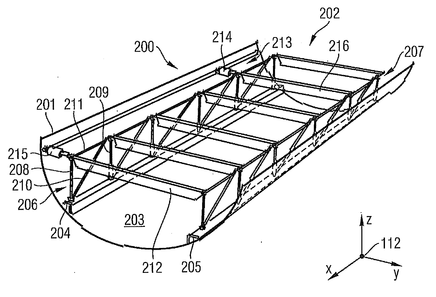
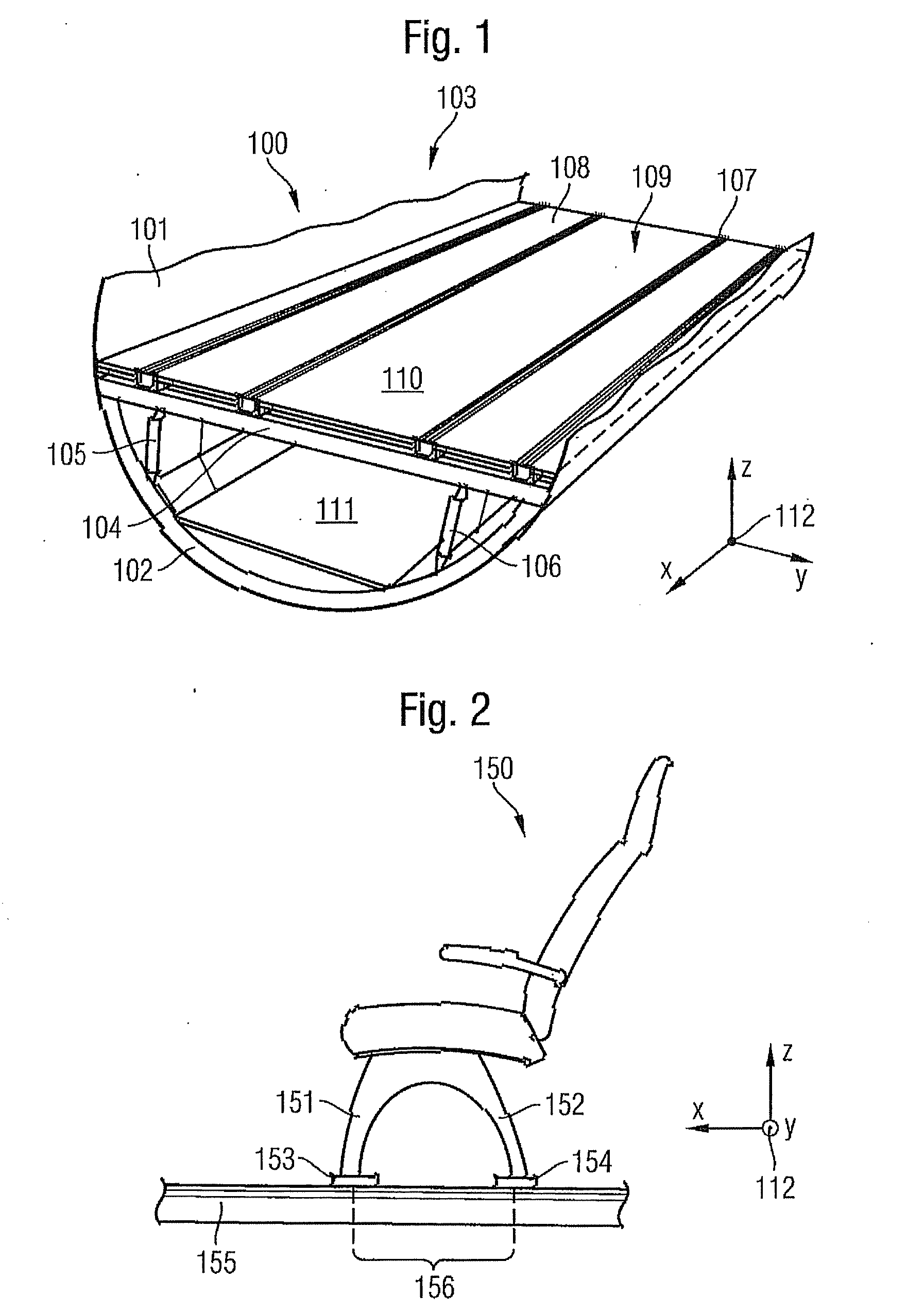
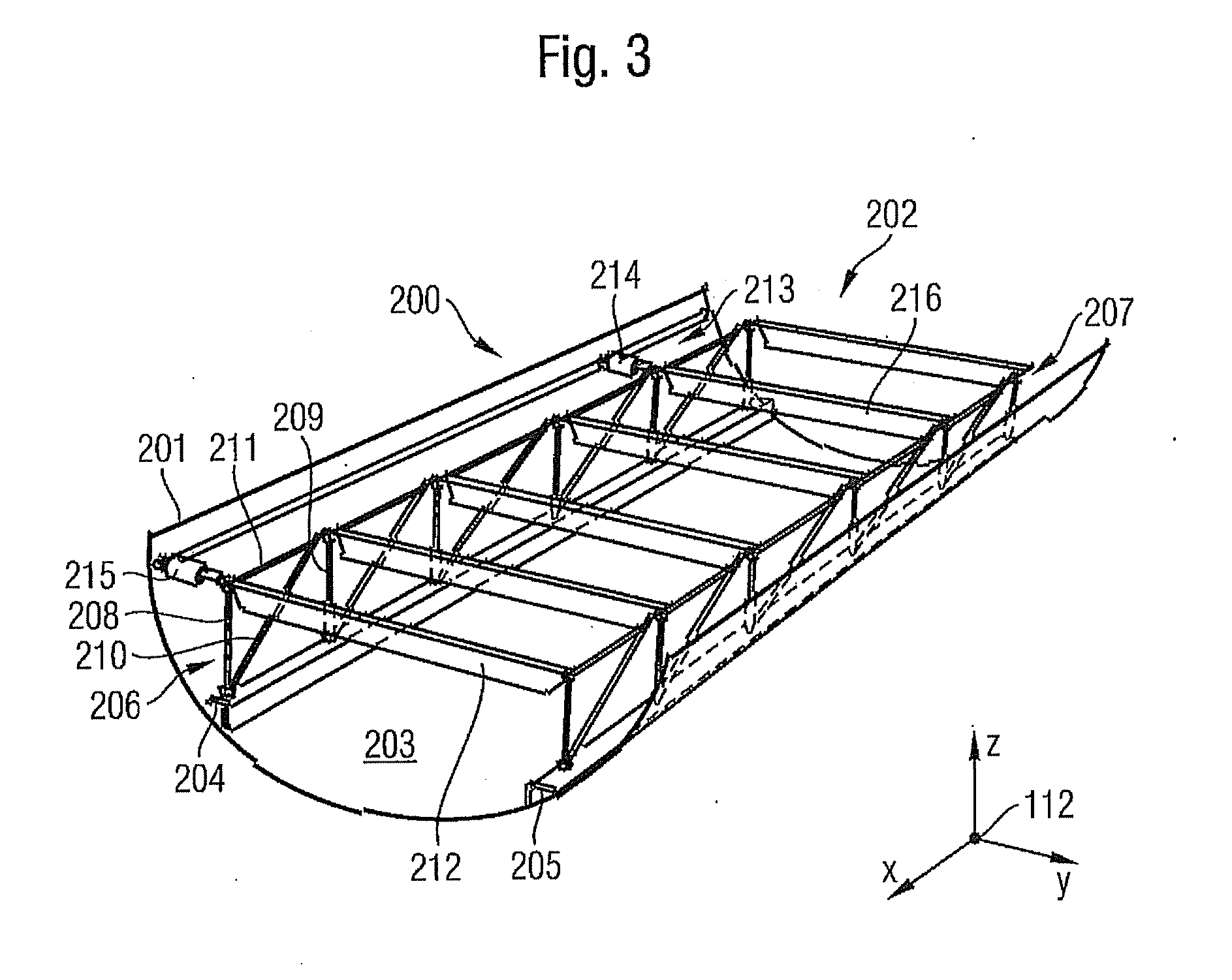
[0048]FIG. 1 is a perspective view of a floor system according to the prior art. A fuselage airframe 100 of an aircraft (not shown) with a substantially circular cross-sectional geometry comprises, inter alia, a fuselage cell skin 101 with a plurality of annular formers arranged therein, of which only the foremost annular former 102 is provided with a reference numeral. A floor system 103 of the fuselage airframe 100 comprises, inter alia, a plurality of crossbars 104. The crossbar 104 is connected on both sides to an annular former 102. In addition, the crossbar 104 is supported downwards by two conventional Samer rods 105, 106 arranged between the crossba...


PUM


Abstract

A floor system for a fuselage section of an aircraft is provided. The floor system has an essentially self-supporting design and is substantially mechanically separate from the fuselage section as primary structure. Consequent to the free or self-supporting design of the floor system in the fuselage cell, the layout of the floor system along an aircraft axis can be matched to customer specifications in a simple manner without reference to structural boundary conditions of the fuselage structure. A floor surface for the floor system is formed from a number of floor elements which can be fitted with functional elements, wherein filling of empty spaces or cavities can be achieved with a number of floor equalisation elements. As the floor elements have a relatively large support or fixing surface the loads induced by the functional elements are introduced into the floor system distributed over a large area such that the structural components thereof can be of a structurally lighter and thus weight-saving size.

Description

CROSS-REFERENCE TO RELATED APPLICATIONS[0001]This application is a continuation of PCT / EP 2009 / 050128 filed Jan. 7, 2009 and claims the benefit of U.S. Provisional Application No. 61 / 063,896, filed Feb. 7, 2008 and German Patent Application No. 10 2008 007 838.7, filed Feb. 7, 2008, the entire disclosures of which are herein incorporated by reference.FIELD OF THE INVENTION[0002]The invention relates to a complex floor system for a fuselage airframe of an aircraft comprising a large number of floor members to form a floor surface.[0003]For reasons of comfort and due to use at high altitudes, to optimise use present-day passenger aircraft generally have compression-proof fuselage airframes, the internal pressure of which, at a flight altitude of, for example 12,000 m corresponds to an air pressure which prevails at approximately 1,800 m. The fuselage airframe of an aircraft is formed using a plurality of substantially barrel-shaped fuselage sections which are arranged in tandem and ar...

Claims


Application Information

Patent Timeline
IPC IPC(8): B64C1/18
CPCB64C1/18Y02T50/46B64D11/0696Y02T50/40
Inventor HAACK, CORDSCHUMACHER, MARKUSMUIN, ANDREWSCOLEY, IAN
Owner AIRBUS OPERATIONS GMBH
Why Eureka
Try Eureka