
Optical scanning device and image forming apparatus

Inactive Publication Date: 2011-01-20
RICOH KK
View PDF15 Cites 5 Cited by
  • Summary
  • Abstract
  • Description
  • Claims
  • Application Information

AI Technical Summary

Benefits of technology

[0018]According to one aspect of the present invention, there is provided an optical scanning device comprising: a light source; an optical deflecting unit that deflects a light beam emitted from the light source to scan on a scanning surface in main-scanning direction; and a scanning optical system that includes a first scanning lens and a second scanning lens that converge the light beam deflected by the optical deflecting unit onto the scanning surface, wherein distance between an exit surface of the first scanning lens and an

Problems solved by technology

However, positions and geometry of the lenses in the optical scanning device disclosed in Japanese Patent Application Laid-open No. 2001-296491 are disadvantageous in involving considerably large sub-scanning lateral magnification.
This disadvantage can be prevented by achieving high precision in dimensional accuracy, processing accuracy, and accuracy in installation positions of polygon mirror and optical system upstream, in optical path, of the optical deflector; however, this countermeasure can lead to additional manufacturing cost.
However, use of a plurality of scanning lenses undesirably reduces flexibility in layout design of a reflecting mirror, which is disclosed in an optical scanning device configured according to the technique disclosed in Japanese Patent Application Laid-open No. 2004-086019.
Particularly in a color laser printer or the like that includes reflecting mirrors for four stations, flexibility in layout design of the reflecting mirrors is much reduced, which is disadvantageous.
Because arranging the reflecting mirror downstream of the second scanning lens can shorten distance between mirrors, particularly in an optical system that includes two or three reflecting mirrors, this can disadvantageously make it difficult to ensure space for use in adjusting layout design of the reflecting mirrors.
However, this disadvantage has a large effect on the optical scanning device configured as disclosed in Japanese Patent Application Laid-open No. 2004-086019, because the optical scanning device has reduced flexibility in layout design of the reflecting mirrors.
The reflecting mirror can be positioned between the two scanning lenses rather than downstream from the second scanning lens; however, this arrangement is disadvantageous in that light beam can obliquely fall on the second scanning lens, resulting in curved scanning line or the like.
To position the second scanning lens downstream from the reflecting mirror, at which scan width is relatively large, it is necessary to employ a lens of a greater length as the second scanning lens; this can lead to additional manufacturing cost.
On the other hand, disadvantageously can reduce flexibility in the layout design of the reflecting mirror, when arranging the second scanning lens near the endpoint of the optical path through which light beam travels from the optical deflector to the scanning surface to place higher priority on reduction in sub-scanning-direction lateral magnification.

Method used


Image

  • Optical scanning device and image forming apparatus
  • Optical scanning device and image forming apparatus
  • Optical scanning device and image forming apparatus

Examples


Embodiment Construction

Optical Scanning Device:

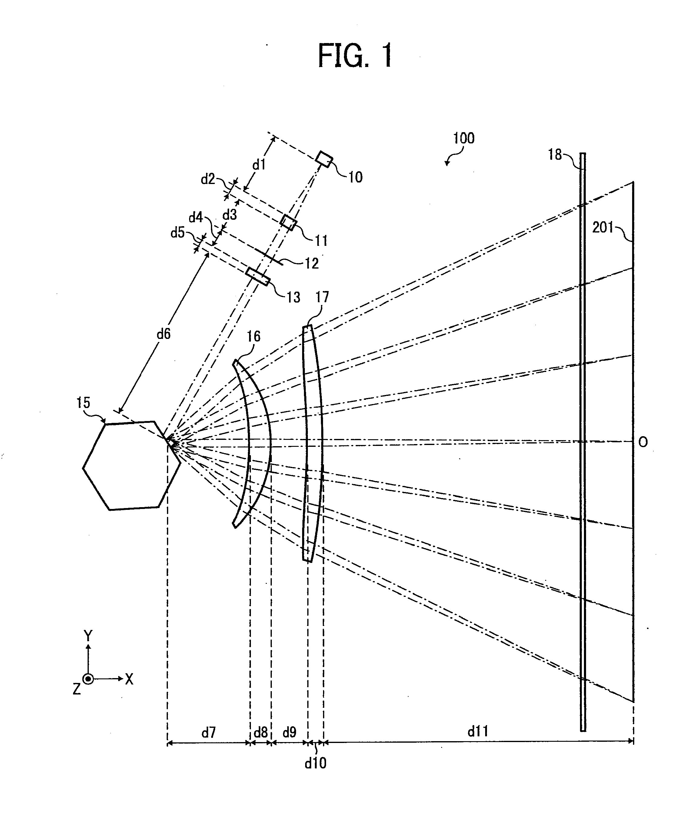
[0029]Exemplary embodiments of optical scanning device according to the present invention are described in detail below with reference to the accompanying drawings.

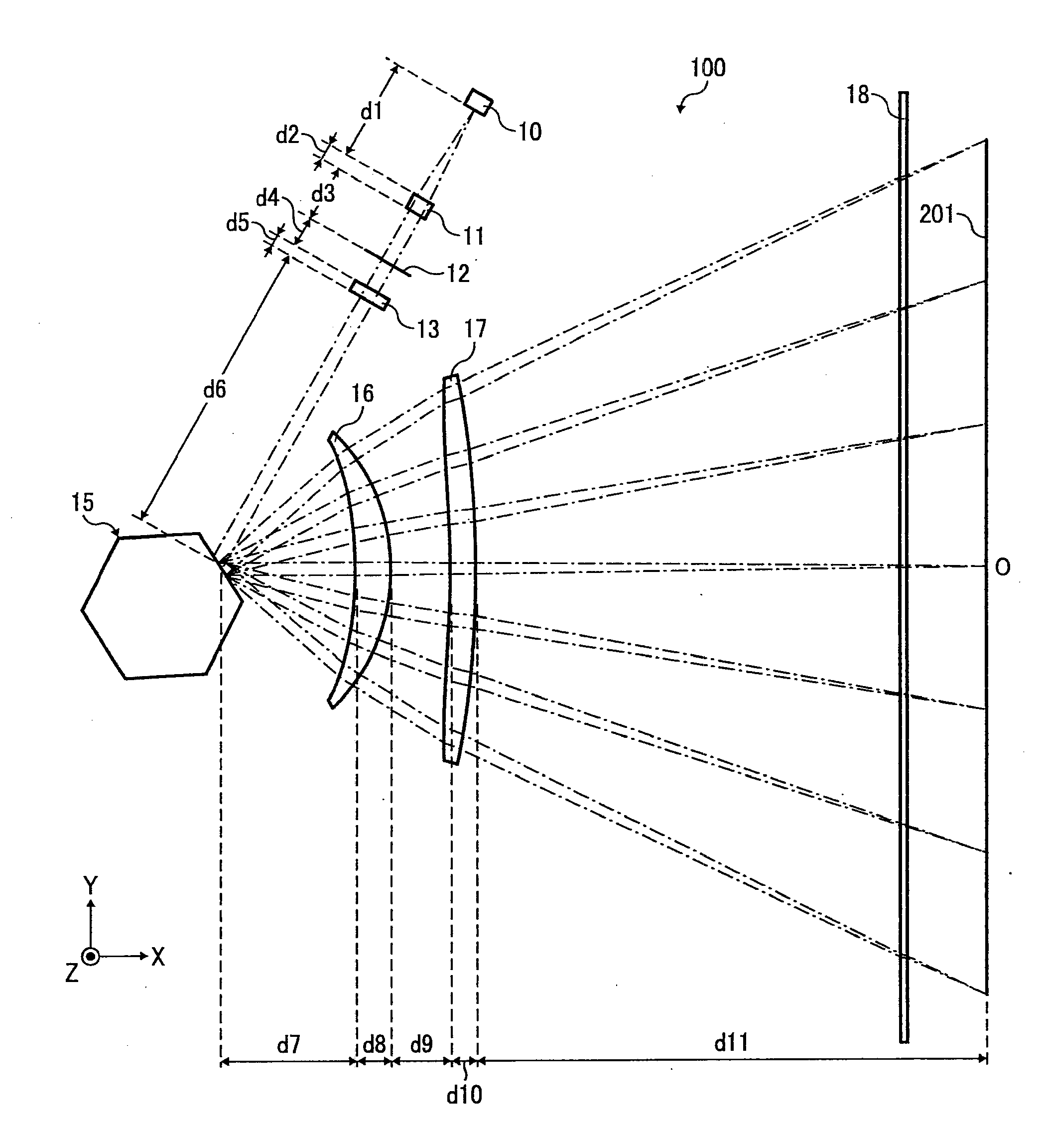
[0030]As illustrated in FIG. 1, an optical scanning device 100 according to an embodiment includes a light source 10, a coupling lens 11, an aperture member 12, a line-image-forming lens 13, and a polygon mirror 15 serving as an optical deflector, a first scanning lens 16, a second scanning lens 17, and a dust-proof glass member 18. Arranged are the coupling lens 11, the aperture member 12, the line-image-forming lens 13, and the polygon mirror 15 in this order from the light source 10 in a direction at a 60-degree angle down from the leftward direction. Arranged are the first scanning lens 16, the second scanning lens 17, and the dust-proof glass member 18 in this order in the positive X direction relative to the polygon mirror 15. An optical scanning is performed by causing a light beam emitted f...


PUM


Abstract

An optical scanning device includes: a light source; an optical deflecting unit that deflects a light beam emitted from the light source to scan on a scanning surface in main-scanning direction; and a scanning optical system that includes a first scanning lens and a second scanning lens that converge the light beam that is deflected onto the scanning surface. Distance between an exit surface of the first scanning lens and an incident surface of the second scanning lens is shorter than distance between a deflection facet of the optical deflecting unit and an incident surface of the first scanning lens, an exit surface of the second scanning lens is nearer to the deflection facet than a midpoint between the deflection facet and the scanning surface, and an image-surface-side principal point of the scanning optical system in sub-scanning direction is nearer to the scanning surface than the midpoint.

Description

CROSS-REFERENCE TO RELATED APPLICATIONS[0001]The present application claims priority to and incorporates by reference the entire contents of Japanese Patent Application No. 2009-165537 filed in Japan on Jul. 14, 2009.BACKGROUND OF THE INVENTION[0002]1. Field of the Invention[0003]The present invention is directed generally to optical scanning device that has great flexibility in layout design of scanning optical system and narrow variation in beam-spot size, and is directed to image forming apparatus that uses the optical scanning device.[0004]2. Description of the Related Art[0005]In a typical optical scanning device for use in a laser printer, an optical plotter, a digital copying machine, a facsimile apparatus, or the like, optical scanning is performed such that a light beam from a light source device is caused to strike an optical deflector, such as a polygon mirror, to be deflected thereby and thereafter to travel through a scanning optical system arranged downstream in optica...

Claims


Application Information

Patent Timeline
IPC IPC(8): B41J2/435G02B26/08
CPCG02B26/125B41J2/471
Inventor ARAI, NOBUYUKI
Owner RICOH KK
Learn More