Machine tool with a tool changing device

a technology of tool changing device and machine tool, which is applied in the direction of metal-working holders, positioning apparatuses, supports, etc., can solve the problems of inability or possible, and achieve the effect of quick exchange and high availability of tools

Active Publication Date: 2011-01-20
GROB WERKE & K G
View PDF16 Cites 11 Cited by
  • Summary
  • Abstract
  • Description
  • Claims
  • Application Information

AI Technical Summary

Benefits of technology

[0036]In a preferred embodiment of the invention it is provided that the tool magazine and the tool change device are arranged on a common carrier. Therefore it is possible to pre-fabricate this combined constructive unit separately, and to put it module-like in the machine tool. It is in particular possible, to chose a modular construction in order to put thus, for example, a large number of pre-fabricated carriers in different tool magazines. By the considerable interaction of th

Problems solved by technology

This kinematic arrangement, however, is inflexible and makes it impossible or possible only with great effort that multiple-piec

Method used


Image

  • Machine tool with a tool changing device
  • Machine tool with a tool changing device
  • Machine tool with a tool changing device

Examples


Embodiment Construction

[0043]In the Figs. identical or corresponding elements each are indicated with the same reference numbers, and are therefore, if not useful, not described again.

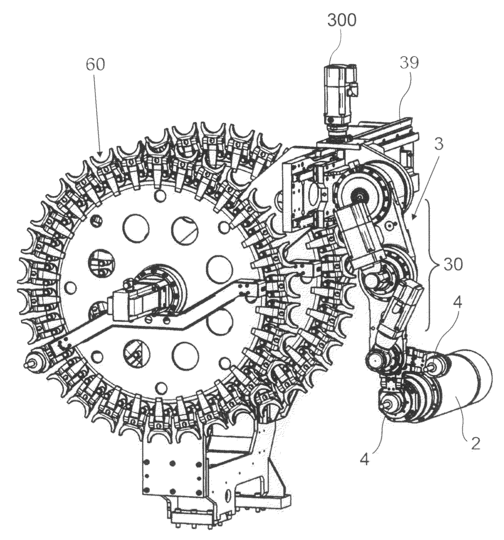
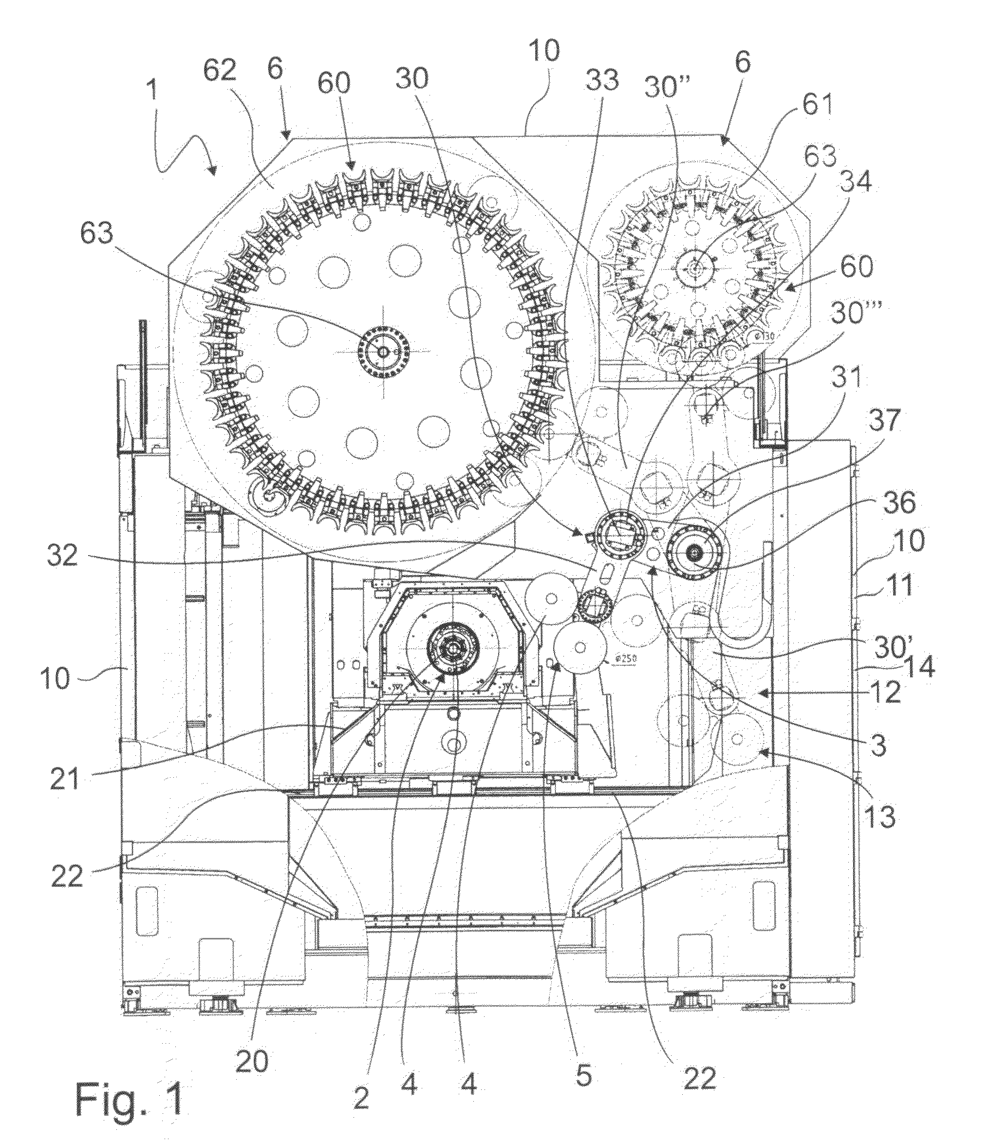
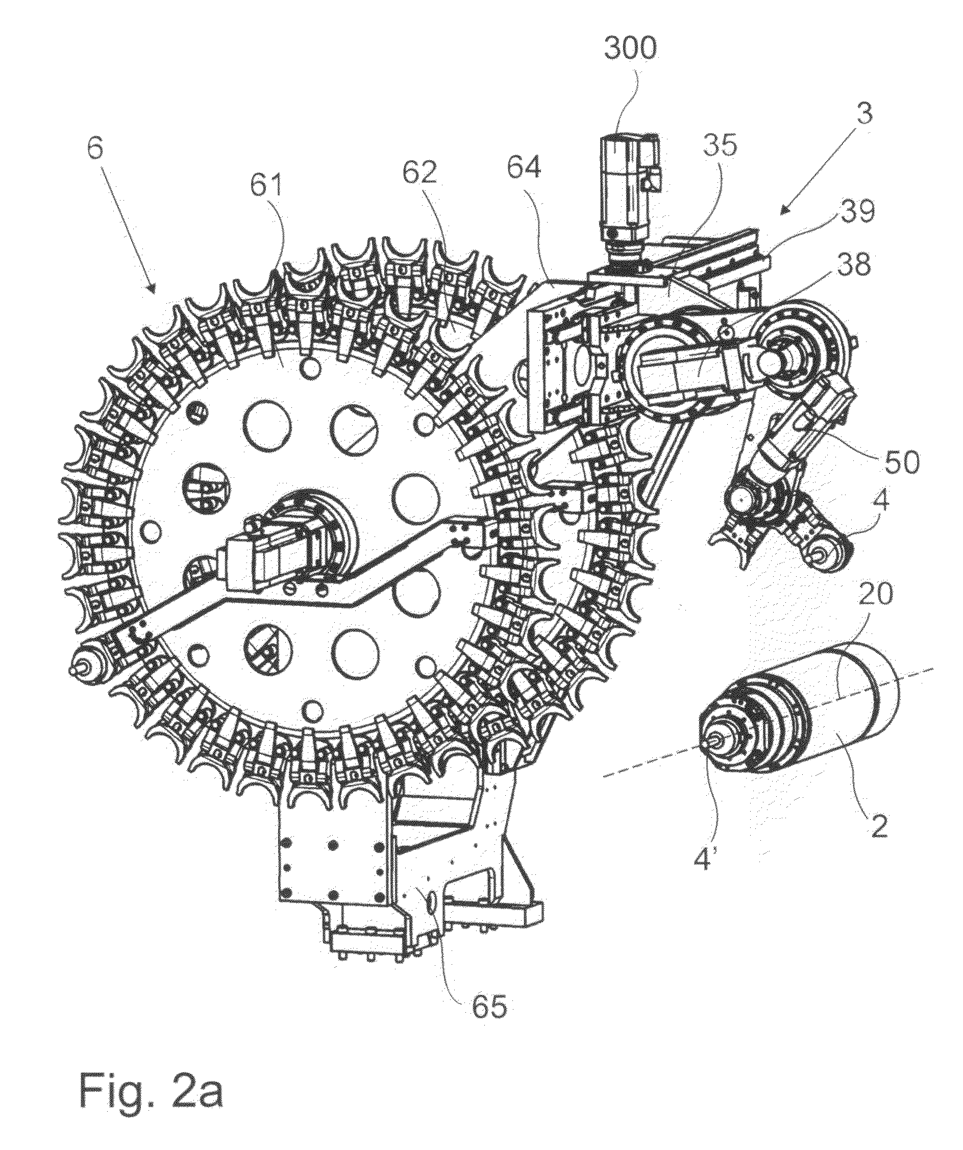
[0044]In FIG. 1 the machine tool 1 according to the invention is shown schematically. The different elements of the machine tool 1 are supported by a machine frame 10 which also comprises, as shown here, the machine housing. The machine frame here encloses the space within which the different elements of the machine tool are arranged. These are, among others, the tool spindle 2, the tool change device 3 as well as the tool magazine 6, which consists, in the example shown here, of two tool magazine parts 61, 62.

[0045]The view chosen in FIG. 1 makes a view in the direction of the spindle axis 20 (extending rectangular to the surface of the sheet) from the front in the machine tool 1 possible. On the right beside it and slightly higher arranged than the spindle axis 20 the tool change device 3 is provided.

[0046]The tool change ...


PUM


Abstract

The invention refers to a machine tool where in a machine frame a tool spindle is provided. In the machine tool a tool change device for at least one machining tool is arranged. The tool spindle consists of a lug with at least two members wherein the lug holds the tool carrier receiving the machining tool. The two members are connected flexibly to each other by a bent joint.

Description

[0001]The invention refers to a machine tool comprising a tool spindle, and at least one machining tool can be changed or exchanged in the tool spindle by a toll change device provided in the machine tool, and the tool spindle sets the machining tool for machining purposes in rotation around a spindle axis.BACKGROUND OF THE INVENTION[0002]Machine tools mentioned above are sufficiently known, for example for metal-cutting material machining. They are used, for example, as machining units or as machining centers, in particular in the field of metal working. A characteristic of machine tools of this kind is that the tool change process has to be carried out as fast as possible in order to minimize standstill times of the machine tool. In order to guarantee, on the one hand, a high variability in machining with machine tools of this kind, and, on the other hand, to accelerate the tool change process accordingly, it is known to provide in the machine tool tool magazines in which a number...

Claims


Application Information

Patent Timeline
IPC IPC(8): B23Q3/157
CPCB23Q3/1554Y10T483/175Y10T483/1748B23Q3/15539B23Q2003/155418B23Q2003/155428B23Q2003/155439Y10S483/902Y10S901/23Y10S901/28Y10S901/41Y10T483/115Y10T483/1767Y10T483/1779Y10T483/1786Y10T483/1836Y10T483/1845Y10T483/1882B23Q3/15713B23Q3/15766B23Q11/08B23Q11/0883B23Q11/0891
Inventor GROB, BURKHART
Owner GROB WERKE & K G
Why Eureka
Try Eureka