
Guide pin placement for hip resurfacing

a technology for placing guide pins and hips, applied in the field of hip surgery, can solve the problems of affecting the accuracy of hip resurfacing, so as to achieve easy neck positioning and facilitate operation.

Inactive Publication Date: 2011-01-20
WRIGHT MEDICAL TECH
View PDF21 Cites 9 Cited by
  • Summary
  • Abstract
  • Description
  • Claims
  • Application Information

AI Technical Summary

Benefits of technology

[0013]It is an object of the invention to provide a less invasive approach for establishing the position of a guide pin for use in a femoral resurfacing procedure.
[0015]It is an object of the invention to provide guide pin placement instruments and procedures that reduce exposure, risk of mal-alignment, soft tissue trauma, bleeding, pain, time of recovery and other factors associated with total or partial hip resurfacing.
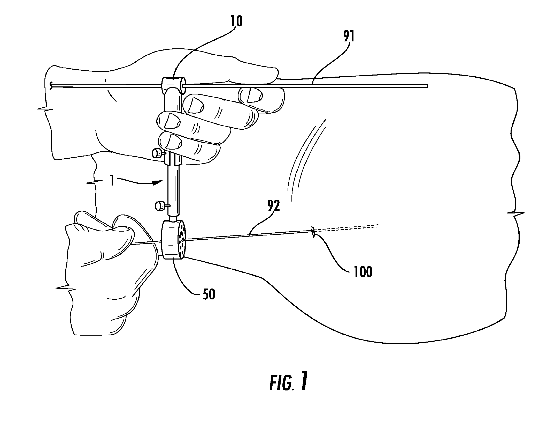
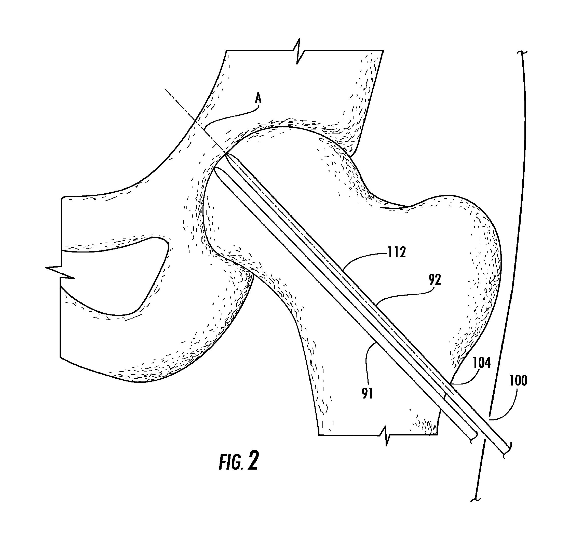
[0023]In total or partial hip resurfacing, it is desirable to use a retrograde approach to centering the guide pin because once the center of the neck has been established, the operation is much easier. By using the techniques described herein to shoot a pin through the lateral femoral cortex of the femur under flouro, a surgeon is able to find the neck easily in two planes.

Problems solved by technology

However, assessing the femoral head, neck relationship intra-operatively after dislocation and then placing the guide pin in an antegrade fashion can be somewhat complicated and unreliable.
A relatively large exposure is required, particularly for inexperienced surgeons.
A large exposure increases bleeding, pain and the risk of infection.
Such large holes may lead to fracture in the sub-trochanteric region.
Additionally, the procedures are not done preoperatively, and do not provide teachings concerning the placement of guide pins for use in surface replacement arthroscopy of the type described in Amstutz.

Method used


Image

  • Guide pin placement for hip resurfacing
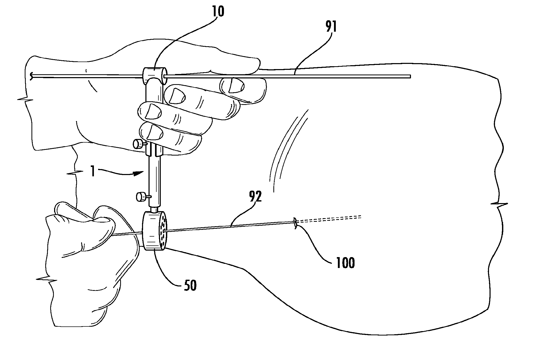
  • Guide pin placement for hip resurfacing
  • Guide pin placement for hip resurfacing

Examples


Embodiment Construction

[0029]In the following detailed description of the preferred embodiments, reference is made to the accompanying drawings which form a part hereof, and in which are shown by way of illustration specific embodiments in which the invention may be practiced. It is to be understood that other embodiments may be utilized and structural changes may be made without departing from the scope of the present invention.

[0030]As shown in FIGS. 1-4, the invention provides methods and instruments for precise positioning of a guide pin for use in resurfacing a femoral head and neck. As will be described in further detail below, internal imaging (currently, CRM or fluoroscopy images) and a retrograde approach are used to select and establish the position of a guide pin track 112 in the femoral head 102 and neck 101 prior to opening the hip. As indicated in FIG. 3, the hip is then opened (preferably using a minimally invasive approach, such as an incision of 8 cm or less), a definitive guide pin 192 i...


PUM


Abstract

An instrument for guide pin placement in a femoral head and neck of a patient, the instrument having a reference pin guide member and a retrograde pin guide member adjustably attached to the reference pin guide member. The reference guide pin member has a bore configured for use in positioning and guiding an external reference pin. The retrograde pin guide member has a plurality of retrograde pin bores for use in positioning and guiding a retrograde reference pin into the femoral neck and head of the patient using a retrograde approach. If an initial retrograde reference pin is not positioned properly, one of the plurality of retrograde pin bores is used to insert another retrograde reference pin in a more desirable position using a retrograde approach.

Description

CROSS REFERENCE TO RELATED APPLICATIONS[0001]This application is a continuation of and claims priority to Application Ser. No. 60 / 793,795, filed Apr. 21, 2006, which is pending.STATEMENT REGARDING FEDERALLY SPONSORED RESEARCH OR DEVELOPMENT[0002]Not applicableFIELD OF THE INVENTION[0003]The present invention relates to hip surgery, and more particularly to placement of pin guides for use in hip resurfacing.BACKGROUND OF THE INVENTION[0004]In conventional total hip arthroplasty, the head and neck of the natural femur are removed and replaced with an artificial femoral head and neck. The artificial head and neck are attached to a stem that is secured in the intramedullary canal of the femur. Over the years, total hip arthroplasty has had excellent clinical success. However, various conditions can arise in which it becomes necessary to perform revision surgery on the hip joint. The presence of the implant in the femur can sometimes result in stress shielding, osteolysis or other condit...

Claims


Application Information

Patent Timeline
Patent Type & Authority Applications(United States)
IPC IPC(8): A61B17/56
CPCA61B17/175A61B17/1721
Inventor PENENBERG, BRAD L.
Owner WRIGHT MEDICAL TECH
Learn More