Method and apparatus for home automation and energy conservation

a technology for home automation and energy conservation, applied in the field of system for home automation, can solve the problems of inability system failure to provide intelligent monitoring and control, and very rare accidental events, so as to reduce the energy consumption of a home, reduce the carbon footprint, and reduce the effect of energy costs

Inactive Publication Date: 2011-01-20
GILSTRAP DANIEL
View PDF0 Cites 233 Cited by
  • Summary
  • Abstract
  • Description
  • Claims
  • Application Information

AI Technical Summary

Benefits of technology

[0018]Accordingly, the present invention provides a home automation system and method of controlling a home automation system. The system and method reduces energy consumption of a home that reduces energy costs and decreases the carbon footprint that results from the decreased use o

Problems solved by technology

These systems typically require expensive components that cost tens of thousands of dollars and controllers that require specialized complex programming, thus making them unaffordable and not accessible to the average home owner.
Such systems also fail to provide intelligent monitoring and control in a self learning manner that is affordable, easy to install and that utilizes preexisting components that allow remote access and control of the home automation system.
A skilled attacker could p

Method used


Image

  • Method and apparatus for home automation and energy conservation
  • Method and apparatus for home automation and energy conservation
  • Method and apparatus for home automation and energy conservation

Examples


Embodiment Construction

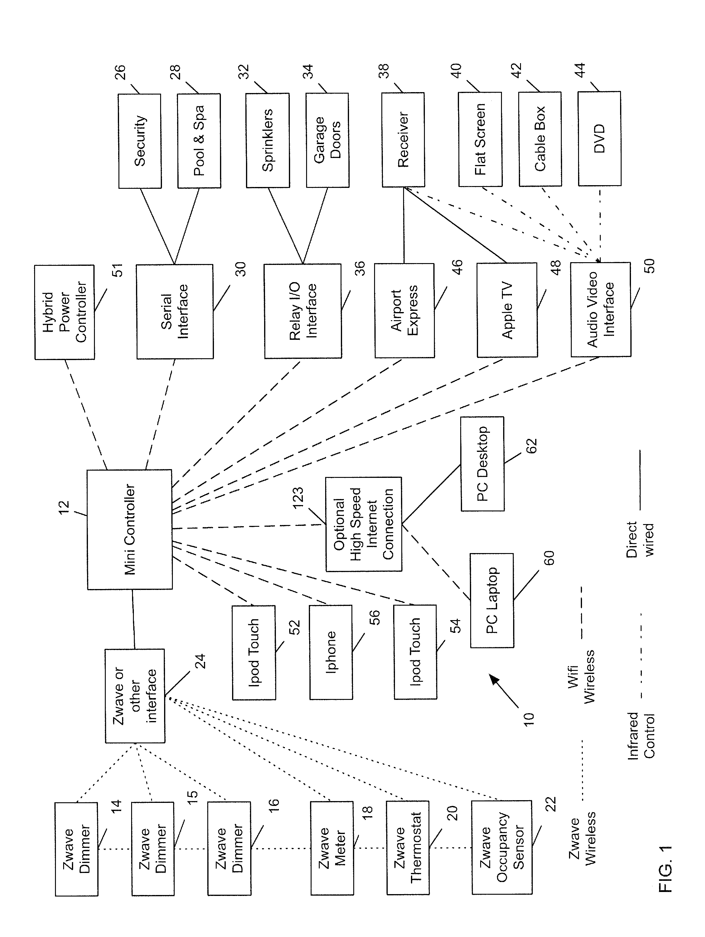
[0046]Referring to the drawings, FIG. 1 is a schematic diagram of a home automation system, generally indicated at 10, in accordance with the principles of the present invention. In the embodiment of the home automation system 10, a controller 12, in the form of a MAC MINI, is employed to operate and control the system 10. Of course, other PCs and PC operating systems may be employed, such a Windows-based PC or Linux-based PC. The controller 12 uses software (as will be described in more detail) to control the various system components. Communications between the controller 12 and the various system components may be wireless (e.g., Z-wave, WI-FI, infrared, RF etc.) or by hard wiring. The system may be in communication with various Z-wave components, such as dimmers 14, 15 and 16, meter 18, thermostat 20 and occupancy 22. The controller 12 uses a Z-wave interface 24 to enable two-way communication between the Z-wave components and the controller 12.

[0047]Other components and compone...


PUM


Abstract

A system for reducing utility consumption of at least one subsystem of a facility is disclosed. A utility meter is coupled to the subsystem for monitoring utility consumption of the subsystem and provides data corresponding to the measured energy consumption. A controller in communication with the subsystem and the energy meter is configured to control the operation of the subsystem by employing an operating protocol with the protocol dependent on the data received from the utility meter. The system measures the reduction in utility consumption and generates a credit based on the measured reduction.

Description

CROSS-REFERENCE TO RELATED APPLICATION [0001]The present application claims priority to U.S. Provisional Patent Application 60 / 080,596 filed on Jul. 14, 2008 to Daniel Gilstrap, the entirety of which is incorporated by this reference.FIELD OF THE INVENTION [0002]The present invention relates generally to systems for home automation, and more specifically, to a system for automating the lighting, climate controls and other devices to decrease energy consumption and increase the home's energy efficiency.BACKGROUND OF THE INVENTION [0003]Various levels of home automation have been available for decades. Such home automation systems have been provided to control lighting, climate control and other household systems. Such systems are typically programmed to operate based upon the desires of the homeowner, such as when to turn lights on and off and the temperature of the living spaces. These systems typically require expensive components that cost tens of thousands of dollars and controll...

Claims


Application Information

Patent Timeline
IPC IPC(8): G06F1/32G06Q99/00
CPCG05B2219/2642G05B15/02
Inventor GILSTRAP, DANIEL
Owner GILSTRAP DANIEL
Why Eureka
Try Eureka