
Battery tester for electric vehicle

a technology for electric vehicles and testers, applied in battery/fuel cell control arrangements, propulsion by capacitors, instruments, etc., can solve problems such as rapid proliferation of hybrid systems

Active Publication Date: 2011-01-20
MIDTRONICS
View PDF140 Cites 44 Cited by
  • Summary
  • Abstract
  • Description
  • Claims
  • Application Information

AI Technical Summary

Problems solved by technology

Due to the increasing price of petroleum, hybrid systems are rapidly proliferating.

Method used


Image

  • Battery tester for electric vehicle
  • Battery tester for electric vehicle
  • Battery tester for electric vehicle

Examples


Embodiment Construction

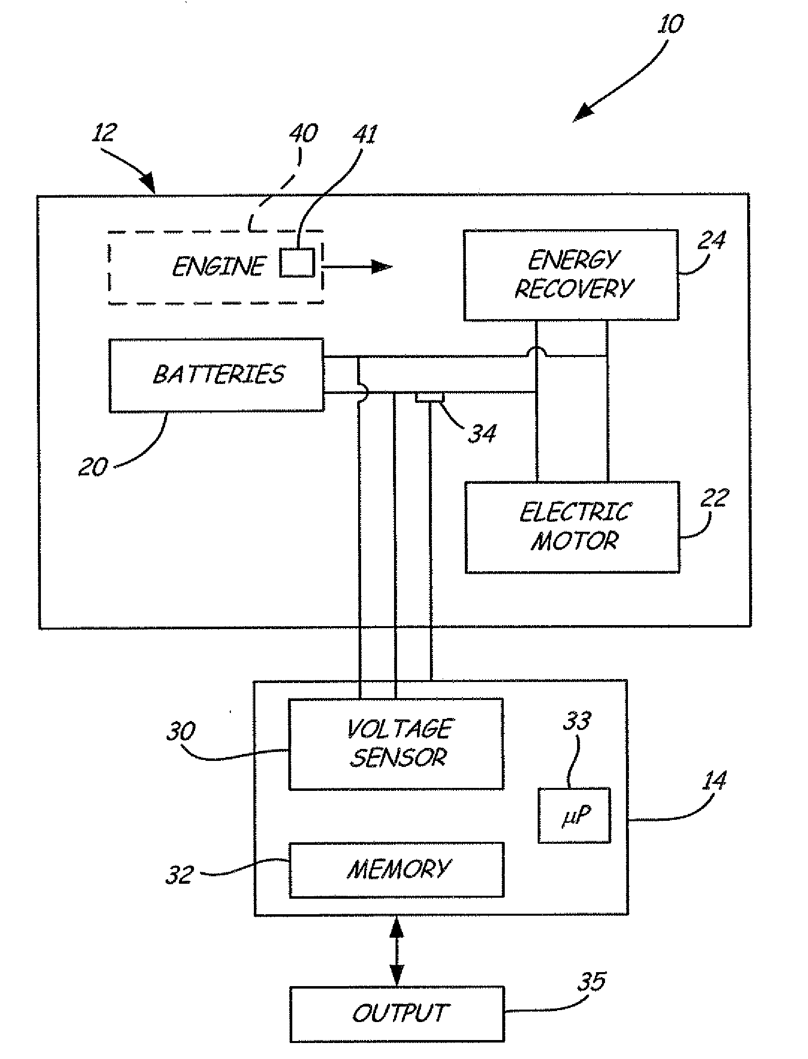
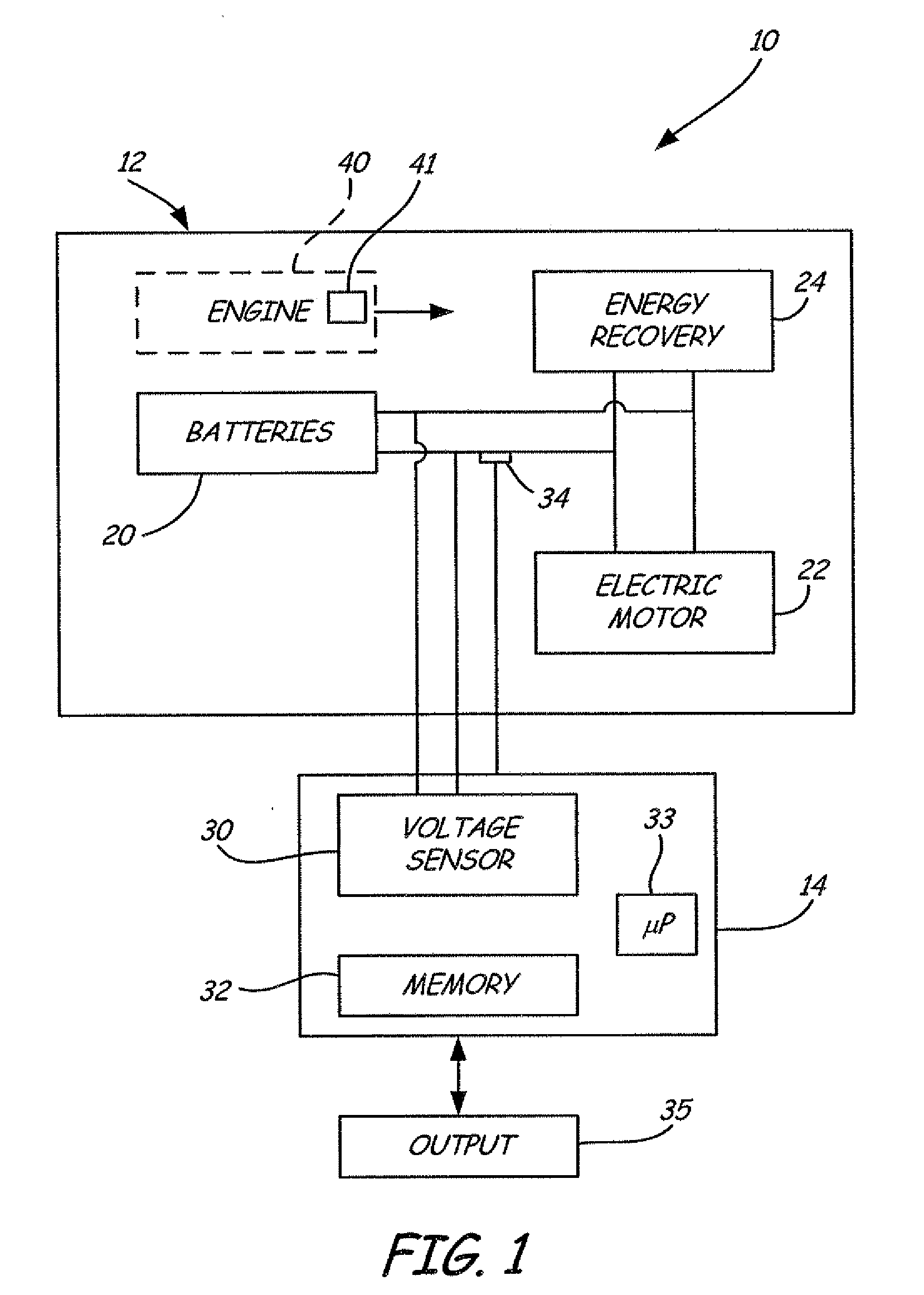
[0010]Electric vehicles and hybrid vehicles are becoming increasingly popular as an alternative to traditional vehicles which are powered solely by an internal combustion engine. In a electric vehicle, a large battery or a group of batteries, or other energy storage device, is used to store electrical energy. The stored electrical power is used by an electric motor to power the electric vehicle.

[0011]In order to increase energy efficiency, some electric vehicles use various techniques to capture or otherwise recover waste energy. This may be referred to as “regeneration”. The recovered energy is typically returned in the battery of the electric vehicle for storage and subsequent use.

[0012]Various techniques are used to recover energy. For example, one common technique is to use the braking system of the electric vehicle to convert vehicle motion into electricity for storage in the battery. This differs from a conventional braking system in which excess energy is vented into the atmo...


PUM


Abstract

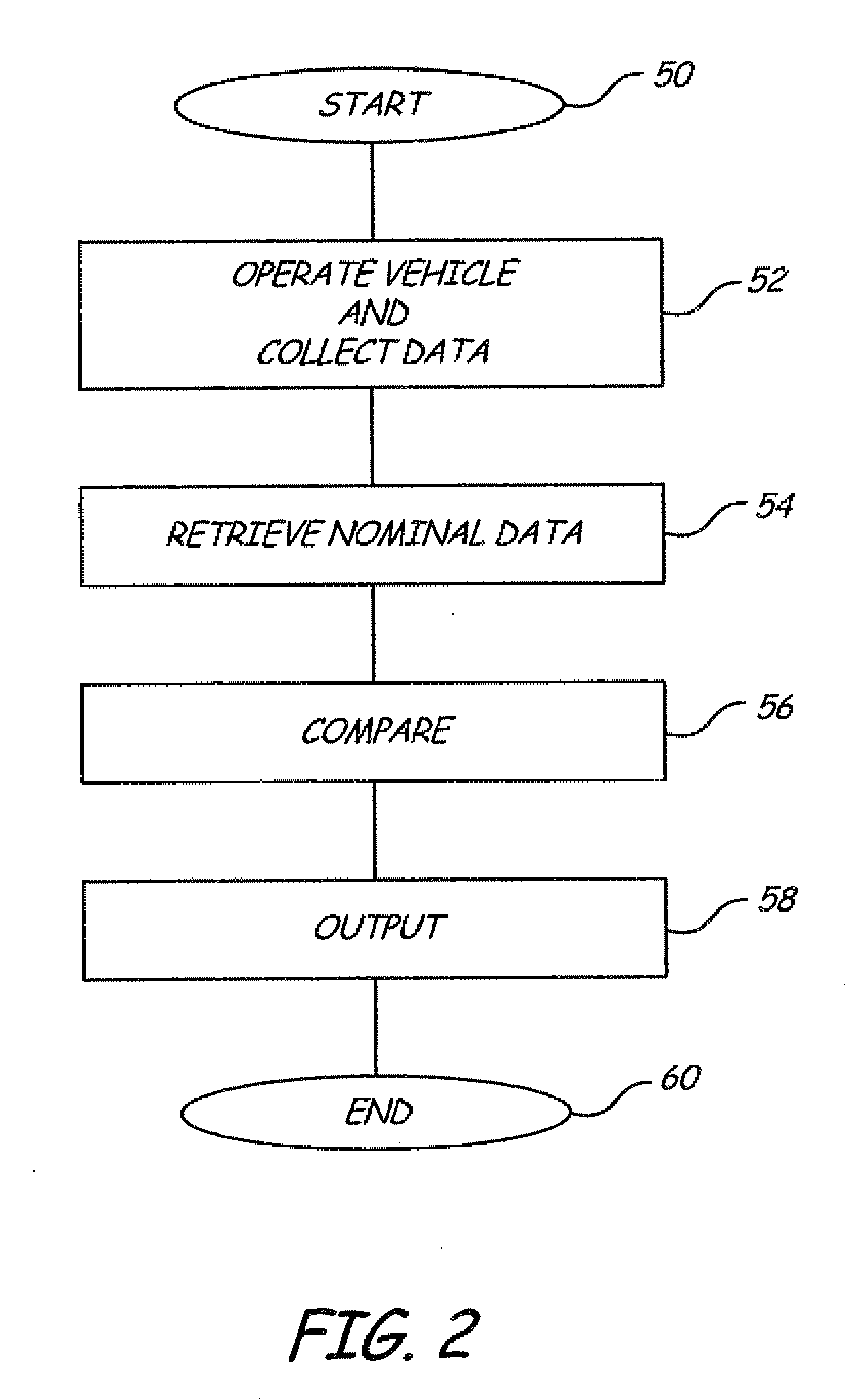
Testing or diagnostics are performed on an electric vehicle. The vehicle is operated and current flow through a system of the vehicle is monitored. A voltage related to the system is also monitored. Diagnostics are provided based upon the monitored voltage and the monitored current.

Description

CROSS-REFERENCE TO RELATED APPLICATION[0001]The present application is a Continuation-In-Part of Ser. No. 12 / 174,894, filed Jul. 17, 2008, which is based on and claims the benefit of U.S. provisional patent application Ser. No. 60 / 950,182, filed Jul. 17, 2007, and U.S. provisional patent application Ser. No. 60 / 970,319, filed Sep. 6, 2007, the contents of which are hereby incorporated by reference in their entirety.BACKGROUND OF THE INVENTION[0002]The present invention relates to test equipment for electric vehicles. More specifically, the present invention relates to a tester for testing electrical systems of an electric vehicle.[0003]Various types of electronic battery tester are known in the art. Electronic battery techniques have been pioneered by Midtronics, Inc. of Willowbrook, Ill. and Dr. Keith S. Champlin. Examples are shown and described in U.S. Pat. No. 3,873,911, issued Mar. 25, 1975, to Champlin; U.S. Pat. No. 3,909,708, issued Sep. 30, 1975, to Champlin; U.S. Pat. No. ...

Claims


Application Information

Patent Timeline
IPC IPC(8): G06F19/00B60L11/00B60L50/16
CPCB60L1/003Y02T10/70B60L1/14B60L3/0046B60L3/12B60L7/18B60L11/005B60L11/14B60L11/1857B60L11/1866B60L2240/36B60L2250/16G01R31/007G01R31/3624Y02T10/7005Y02T10/7022Y02T10/7061Y02T10/7077B60L1/02B60L50/16B60L50/40B60L58/16B60L58/22B60L58/10G01R31/3842Y02T10/7072G01R31/385G07C5/0808
Inventor BERTNESS, KEVIN I.
Owner MIDTRONICS
Learn More