
Reducer of electric power steering apparatus

a technology of electric power steering and electric motor, which is applied in mechanical devices, transportation and packaging, and machining details, etc., can solve the problems of unpleasant feeling for the driver during steering wheel operation, rattle noise, etc., and achieves pleasant driving conditions, reduces the noise of rattle, and increases the backlash

Active Publication Date: 2011-01-27
HL MANDO CORP
View PDF5 Cites 24 Cited by
  • Summary
  • Abstract
  • Description
  • Claims
  • Application Information

AI Technical Summary

Benefits of technology

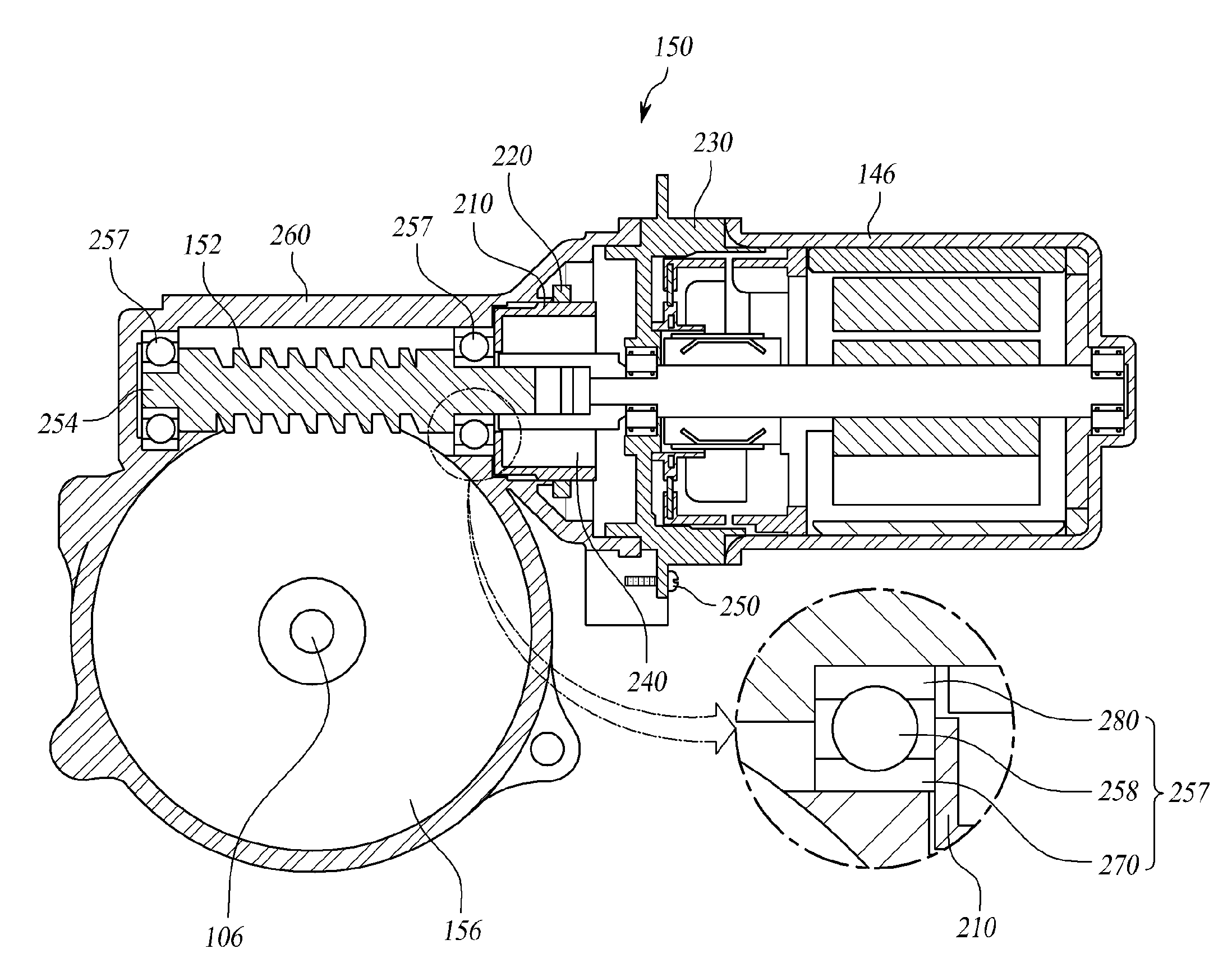
[0016]Accordingly, the present invention has been made to solve the above-mentioned problems occurring in the prior art, and the present invention provides a reducer of an electric power steering apparatus, which can reduce a rattle noise occurring by an increase in backlash caused by abrasion of a worm and a worm wheel, or by an impact transferred from a road via a wheel and a steering shaft, thereby providing a pleasant driving condition to a driver.
[0020]According to the present invention, the reducer of the electric power steering apparatus reduces a rattle noise which occurs by an increase in backlash caused by abrasion of the worm and the worm wheel, or occurs by an impact transferred from a road via a wheel and the steering shaft, thereby providing a pleasant driving condition to the driver.

Problems solved by technology

However, the reducer of the conventional electric power steering apparatus, has a problem in that the progress in the wearing of the worm and the worm wheel rotated by the driving of the motor increases the gap between them, which causes a rattle noise due to the backlash.
Also, there is a problem in that a rattle noise occurs by an impact transferred from a road via a wheel and the steering shaft, thereby causing an unpleasant feeling for the driver during operation of the steering wheel.

Method used


Image

  • Reducer of electric power steering apparatus
  • Reducer of electric power steering apparatus
  • Reducer of electric power steering apparatus

Examples


Embodiment Construction

[0026]Hereinafter, exemplary embodiments of the present invention will be described with reference to the accompanying drawings. In the following description and drawings, the same reference numerals are used to designate the same or similar components, and so repetition of the description on the same or similar components will be omitted. Further, in the following description of the present invention, a detailed description of known functions and configurations incorporated herein will be omitted when it may make the subject matter of the present invention rather unclear.

[0027]In addition, terms, such as first, second, A, B, (a), (b) or the like may be used herein when describing components of the present invention. Each of these terminologies is not used to define an essence, order or sequence of a corresponding component but used merely to distinguish the corresponding component from other component(s). It should be noted that if it is described in the specification that one comp...


PUM


Abstract

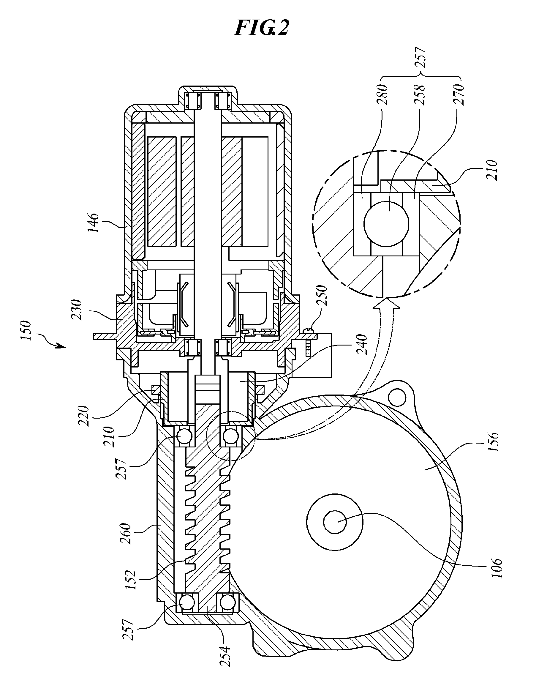
Disclosed is a reducer of an electric power steering apparatus. The disclosed reducer includes: a worm shaft bearing coupled with an end of the worm shaft's motor shaft coupling portion in such a manner that a ball coupled between an inner wheel and an outer wheel supports rotation of the worm shaft; and a first damper and a second damper which are tightly fitted in one side and the other side of the worm shaft bearing, respectively, while being insertedly-coupled with the worm shaft, so as to support the worm shaft and absorb a rattle noise transferred via the worm shaft, wherein each of the first damper and the second damper is provided with supporting plates at both sides thereof, and between the supporting plates, a damper made of an elastic material is coupled and formed. The reducer of the electric power steering apparatus reduces a rattle noise which occurs by an increase in backlash caused by abrasion of the worm and the worm wheel, or occurs by an impact transferred from a road via a wheel and the steering shaft, thereby providing a pleasant driving condition to the driver.

Description

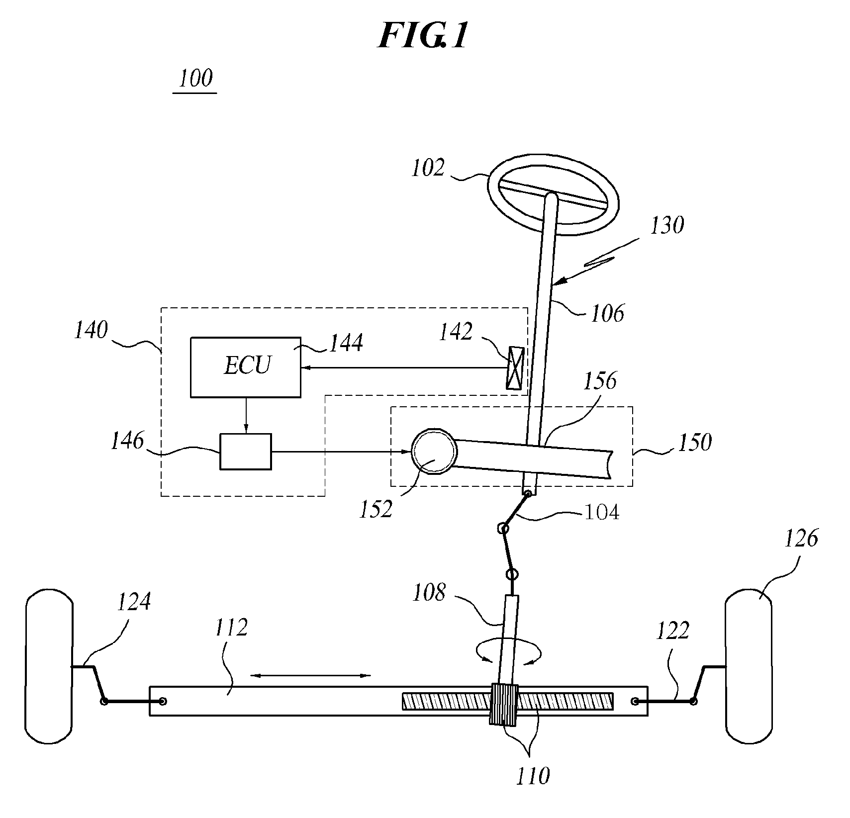
BACKGROUND OF THE INVENTION[0001]1. Field of the Invention[0002]The present invention relates to a reducer of an electric power steering apparatus. More particularly, the present invention relates to a reducer of an electric power steering apparatus, which can reduce a rattle noise occurring by an increase in backlash caused by abrasion of a worm and a worm wheel, or by an impact transferred from a road via a wheel and a steering shaft, thereby providing a pleasant driving condition to a driver.[0003]2. Description of the Prior Art[0004]FIG. 1 shows a configuration view illustrating a conventional electric power steering apparatus. As shown in FIG. 1, an electric power steering apparatus 100 includes a steering system 130 extending from a steering wheel 102 to both side wheels 126, and an auxiliary power mechanism 140 for supplying auxiliary steering power to the steering system 130.[0005]The steering system 130 includes a steering shaft 106 whose one side is connected to the steeri...

Claims


Application Information

Patent Timeline
IPC IPC(8): B62D5/04
CPCB62D5/0409F16H2057/0213F16H57/039F16H57/0006F16C19/06F16C19/54F16C27/066F16C2361/61F16H55/24B62D5/04B62D5/24
Inventor KIM, JI YEOLJUNG, YOUNG SOCKPARK, YOUNG MOON
Owner HL MANDO CORP
Learn More