Locking device

a technology of locking device and locking plate, which is applied in the direction of mechanical control, power plant arrangement/mounting, coupling, etc., can solve problems such as safety detrimen

Inactive Publication Date: 2011-01-27
AIRCELLE
View PDF2 Cites 3 Cited by
  • Summary
  • Abstract
  • Description
  • Claims
  • Application Information

AI Technical Summary

Benefits of technology

[0014]The disclosure provides a locking device making it possible to avoid

Problems solved by technology

To be precise, in the event of poor positioning, it may happen that the locking sys

Method used


Image

  • Locking device
  • Locking device
  • Locking device

Examples


Embodiment Construction

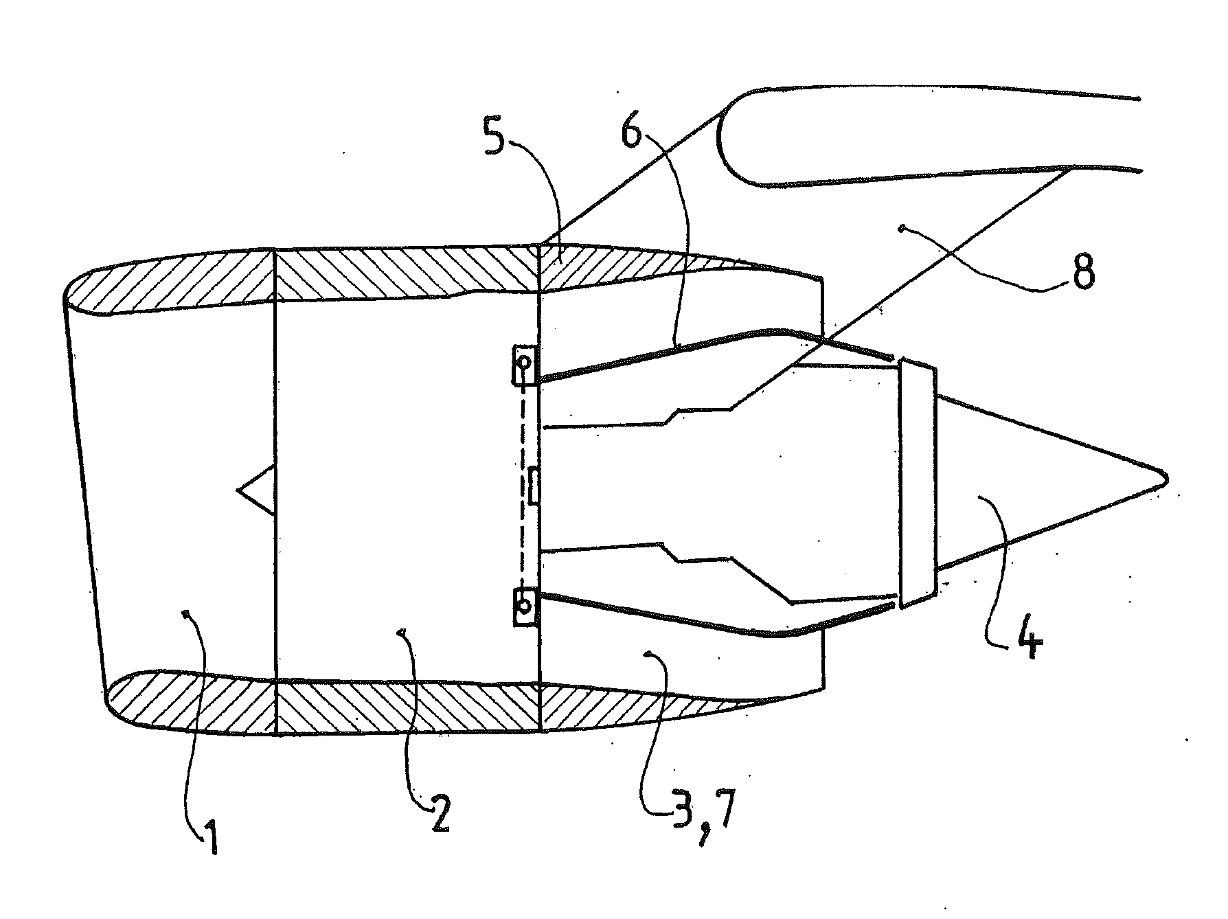
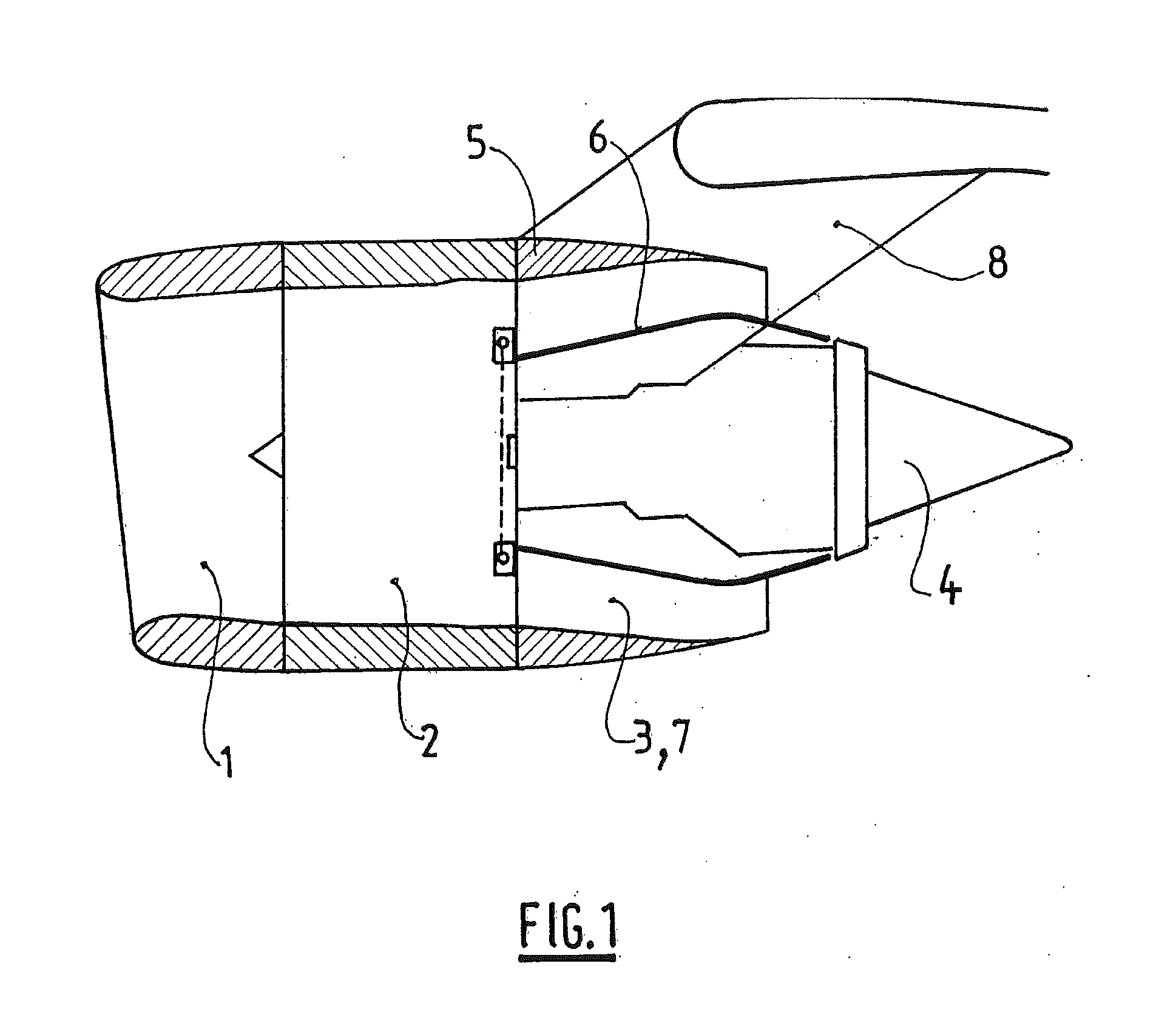
[0030]FIG. 1 illustrates a nacelle according to the invention intended for equipping an aircraft. This nacelle has a tubular structure comprising an air inlet 1 upstream of the turbojet engine, a middle section 2 intended for surrounding a blower of the turbojet engine, a rear section 3 capable of housing thrust reversal means and intended for surrounding the combustion chamber of the turbojet engine, and terminates in an ejection nozzle 4, the outlet of which is located downstream of the turbojet engine.

[0031]The nacelle is intended for housing a double-flow turbojet engine capable of generating, by means of the rotating blades of the blower, a stream of hot air (also called a primary stream) coming from the combustion chamber of the turbojet engine.

[0032]The nacelle has an external structure 5, called an Outer Fixed Structure (OFS), which, with a concentric internal structure 6, called an Inner Fixed Structure (IFS), defines an annular flow channel 7, also called a flow section, a...


PUM


Abstract

The invention relates to a locking device (11) comprising at least one locking system (13) having at least one locking member (17) that can be actuated by linking means (28), the linking means being able to be moved over a defined travel, the movement of the locking means (28) over a first part of the travel enabling the locking member (17) to be actuated, alternately between an unlocked position of the locking member (17) and a locked position thereof, characterized in that the locking system (13) is designed so that the locking member (17) remains immobile during the movement of the linking means (28) over a second portion of the travel, with a view to compensating for the adjustment of the connecting means (28) and also any malpositioning of the locking system (13).

Description

TECHNICAL FIELD[0001]The invention relates to a locking device comprising at least one locking system comprising at least one locking member actuable by connection means, the connection means being displaceable over a specific travel, the displacement of the connection means over a first part of the travel making it possible to actuate the locking member alternately between a position for unlocking the locking member and a position for locking the latter.BACKGROUND[0002]A locking device of this type is used, in particular, in order to equip a nacelle, itself intended for equipping an aircraft.[0003]An aircraft is driven by means of a plurality of turbojet engines, each accommodated in a nacelle which likewise houses an assembly of accessory actuating devices associated with its operation and ensuring various functions when the turbojet engine is in operation or is at a standstill. These accessory actuating devices comprise, in particular, a mechanical system for the actuation of thr...

Claims


Application Information

Patent Timeline
IPC IPC(8): B64D29/00B64C1/16
CPCB64D29/06Y10T403/18E05C1/06E05B53/003
Inventor SOULIER, PASCAL-MARIE PAUL MARCELDE SORBAY, AURELIE
Owner AIRCELLE
Why Eureka
Try Eureka