Device for actuating the wastegate flap of an exhaust gas turbocharger

a technology of wastegate flap and turbocharger, which is applied in the direction of valve operating means/release devices, machines/engines, mechanical apparatus, etc., can solve the problem of dampening of the impact arising during the operation of the devi

Active Publication Date: 2018-02-20
VITESCO TECH GERMANY GMBH
View PDF44 Cites 3 Cited by
  • Summary
  • Abstract
  • Description
  • Claims
  • Application Information

AI Technical Summary

Benefits of technology

[0009]The advantages of the invention are, in particular, that, by using a resiliently mounted ball head rod, an offset arising in the axial direction between the components of the device can be compensated. In particular, deviations in position between the lever and the actuator rod can be compensated. Furthermore, impacts arising during the operation of the device are dampened by the resilient mounting of the ball head rod.
[0010]An additional advantage of the invention is that the precision requirements in assembling the components of the device are reduced since any imprecisions are compensated by the resilient mounting of the ball head rod.

Problems solved by technology

Furthermore, impacts arising during the operation of the device are dampened by the resilient mounting of the ball head rod.

Method used


Image

  • Device for actuating the wastegate flap of an exhaust gas turbocharger
  • Device for actuating the wastegate flap of an exhaust gas turbocharger
  • Device for actuating the wastegate flap of an exhaust gas turbocharger

Examples


Embodiment Construction

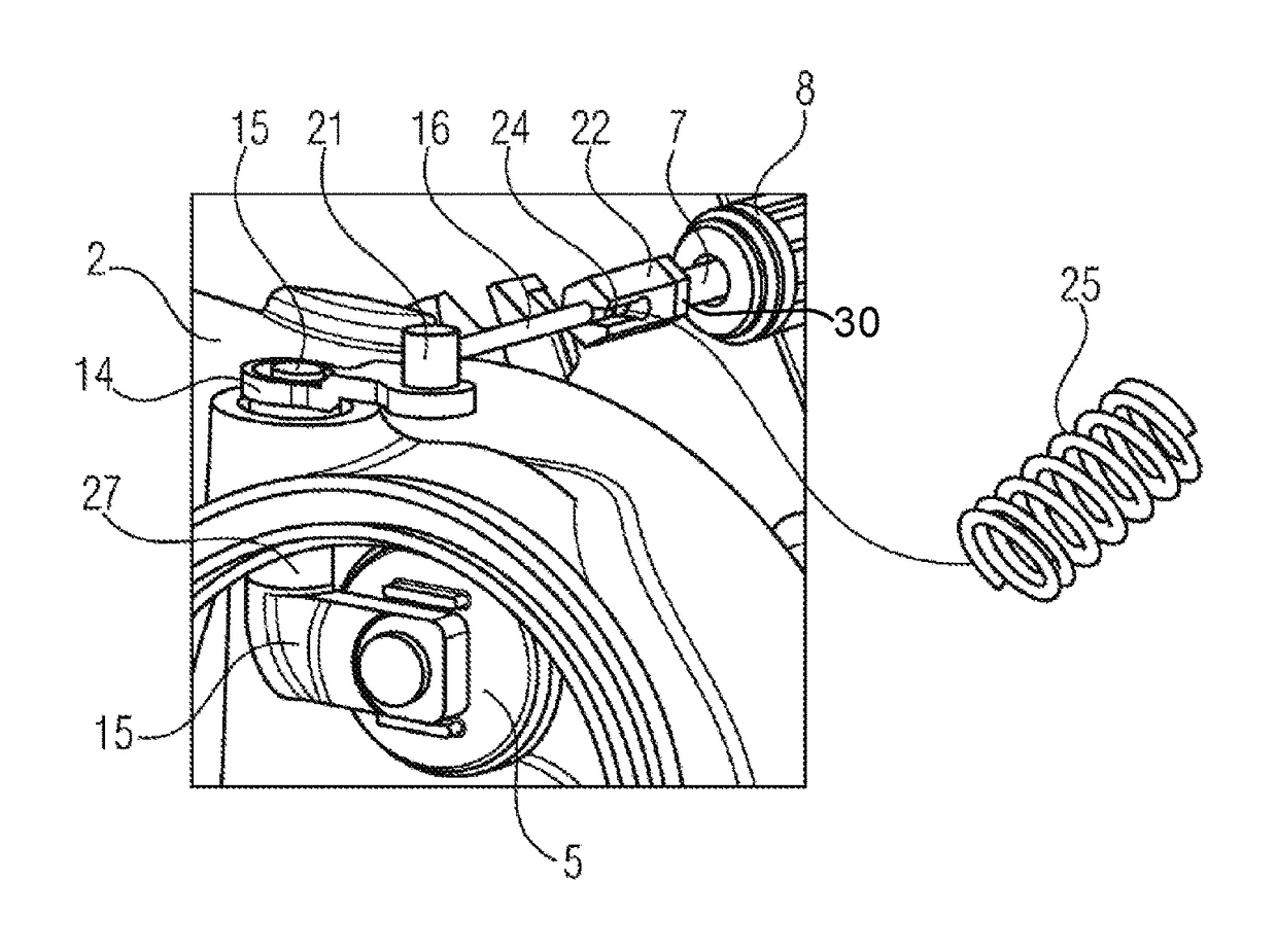
[0019]A device as claimed in the invention for actuating the wastegate flap of the exhaust gas turbocharger of an internal combustion engine contains an actuator having an actuator rod, a lever connected to the actuator rod, a spindle connected to the lever, a wastegate flap which is fastened to the spindle, and a resiliently mounted ball head rod between the actuator rod and the lever.

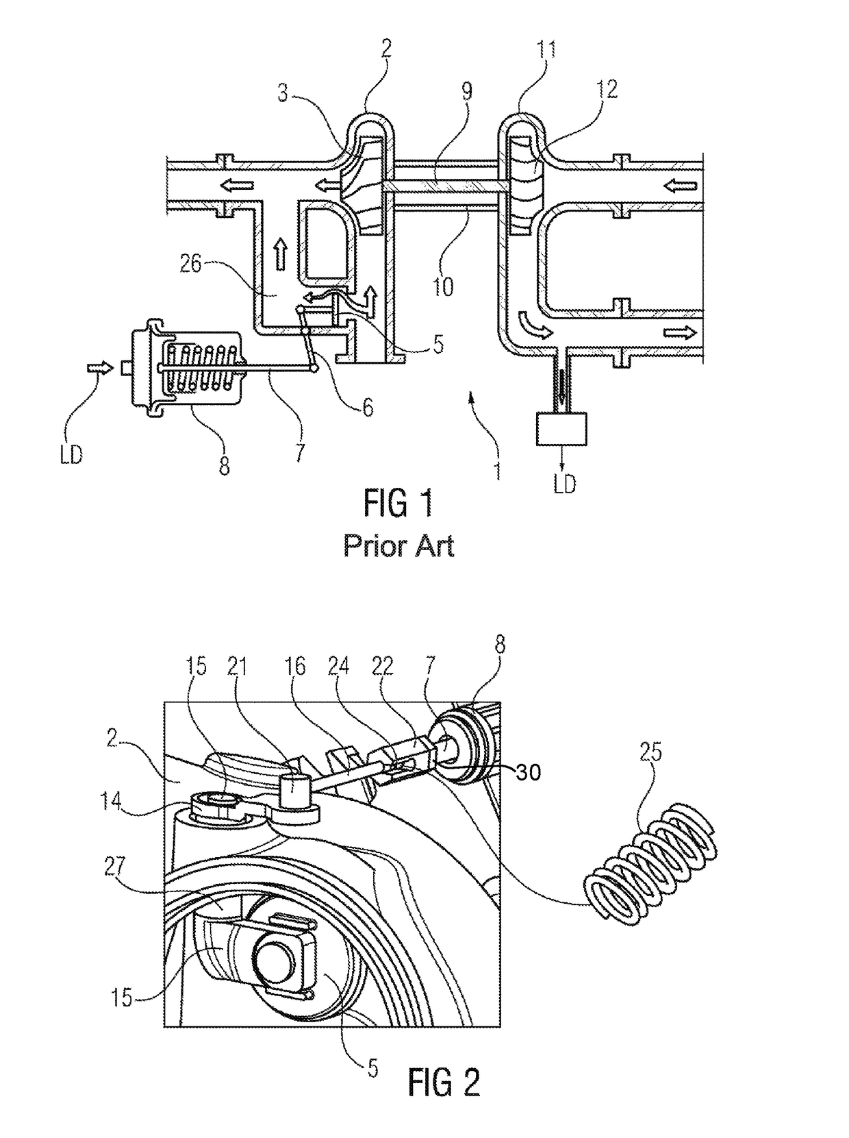
[0020]FIG. 2 shows a sketch to illustrate an exemplary embodiment of such a device as claimed in the invention. In this exemplary embodiment, an actuator 8 is provided that is fastened, for example, to a compressor housing and has an actuator rod 7. This actuator rod is movable in its axial direction in order to open or close a wastegate flap 5 provided in the turbine housing 2 as needed. To this end, the actuator rod 7 is connected to the waste gate flap 5 via a ball head rod 16, a lever 14 and a spindle 15 guided through a sleeve 27.

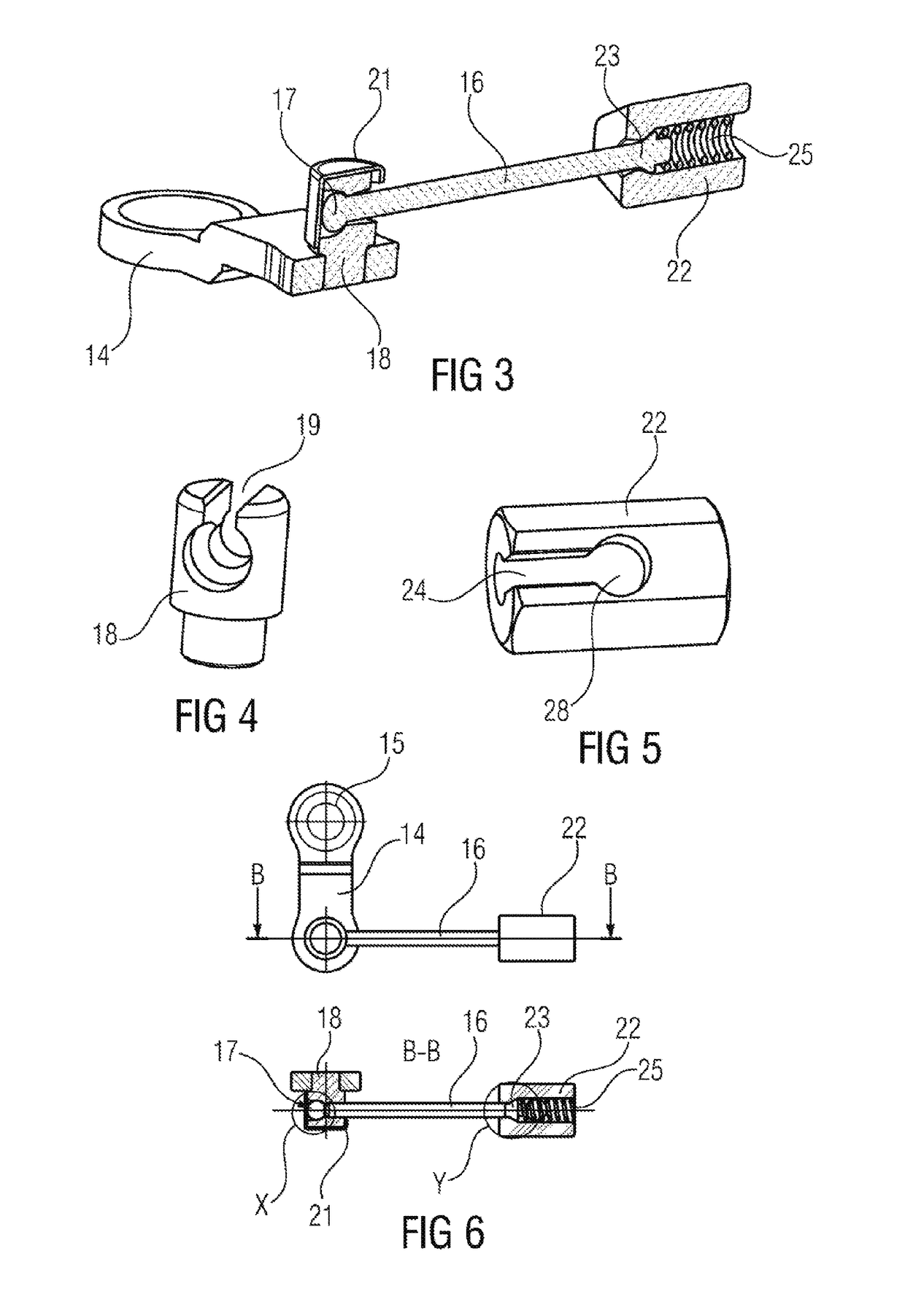
[0021]The end area of the ball head rod 16 facing the actuator rod ...


PUM


Abstract

A device actuates a waste gate flap of an exhaust gas turbocharger of an internal combustion engine. The device has an actuator which has an actuator rod, a lever which is connected to the actuator rod and a spindle which is connected to the lever and to which the waste gate flap is secured. A resiliently mounted ball head rod is provided between the actuator rod and the lever.

Description

BACKGROUND OF THE INVENTIONField of the Invention[0001]The invention relates to a device for actuating the wastegate flap of an exhaust gap turbocharger.[0002]An exhaust gas turbocharger serves to increase the performance and efficiency of piston engines. It has a turbine wheel arranged in a turbine housing, and a compressor impeller arranged in a compressor housing. The turbine wheel and the compressor impeller are arranged on a common shaft which is mounted in a bearing housing arranged between the turbine housing and the compressor housing. The turbine wheel is driven by the exhaust gas stream of the respective motor vehicle and, for its part, drives the compressor impeller via the common shaft. As the engine rotational speed rises, the shaft rotates increasingly faster. The faster the rotation of the shaft, the more air is conveyed by the compressor which, given the increasing amount of exhaust gas, in turn drives the turbine impeller faster. This also increases the friction wit...

Claims


Application Information

Patent Timeline
Patent Type & Authority Patents(United States)
IPC IPC(8): F16K31/44F02B37/18F16C11/08F16C11/06F16K31/163F16K31/52F01D17/10
CPCF02B37/186F16C11/069F16C11/08F16K31/1635F16K31/521F16K31/44Y02T10/144F01D17/105F16C11/086Y02T10/12
Inventor DILALAN, UEMITFERLING, BRUNO
Owner VITESCO TECH GERMANY GMBH
Why Eureka
Try Eureka