Fastening apparatus and method with compensation for load-induced deformation of supporting frame

a technology of supporting frame and load-induced deformation, which is applied in the direction of presses, manufacturing tools, metal-working machine components, etc., can solve the problems of significant deformation of joint quality and undesirable loads on parts, and achieve the effect of reducing the transverse force on the apparatus of the invention, small angular deviation, and better joint-forming results

Active Publication Date: 2007-03-15
NEWFREY
View PDF34 Cites 5 Cited by
  • Summary
  • Abstract
  • Description
  • Claims
  • Application Information

AI Technical Summary

Benefits of technology

[0010] An advantage of the invention is that a smaller angular deviation, and thus better joint-forming results, can be achieved with little effort. The effect of transverse forces on an apparatus of the invention is reduced, and service life is improved.
[0011] When at least two tools having holders of different lengths are used interchangeably, angular deviations resulting from loading during joint forming can be made largely independent of the position of a tool in the apparatus and can be made to lie within a predetermined narrow range.
[0012] By selective variation of the resistance to deformation, in particular the bending strength, various tool holders can be adapted to particular load situations resulting from their individual length in such an manner that essentially the same maximum angular deviations result for each tool holder during joint forming, assuming identical process conditions.
[0013] Also, in accordance with the invention, the different tool holders of a tool holder set can be designed such that their elastic deformation under load at least partially compensates for offset of a joint relative to the frame and does not exceed a predefined maximum value. By limiting the offset, shear forces which load a workpiece and the joint-forming apparatus can be kept small.
[0014] Control of the elastic deformation of a tool holder used in the invention can be achieved by selecting particular structural configurations and / or by controlling material properties of the tool holder.

Problems solved by technology

Such deviations can significantly degrade the quality of a joint and should not exceed a specific amount.
Such offsets can produce undesirable loads on parts being joined and on equipment carrying the frame, for example a robot, and should therefore be kept as small as possible irrespective of the joint positions.

Method used


Image

  • Fastening apparatus and method with compensation for load-induced deformation of supporting frame
  • Fastening apparatus and method with compensation for load-induced deformation of supporting frame
  • Fastening apparatus and method with compensation for load-induced deformation of supporting frame

Examples


Embodiment Construction

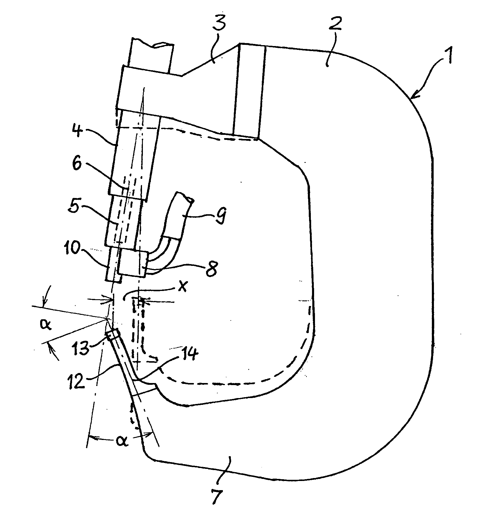
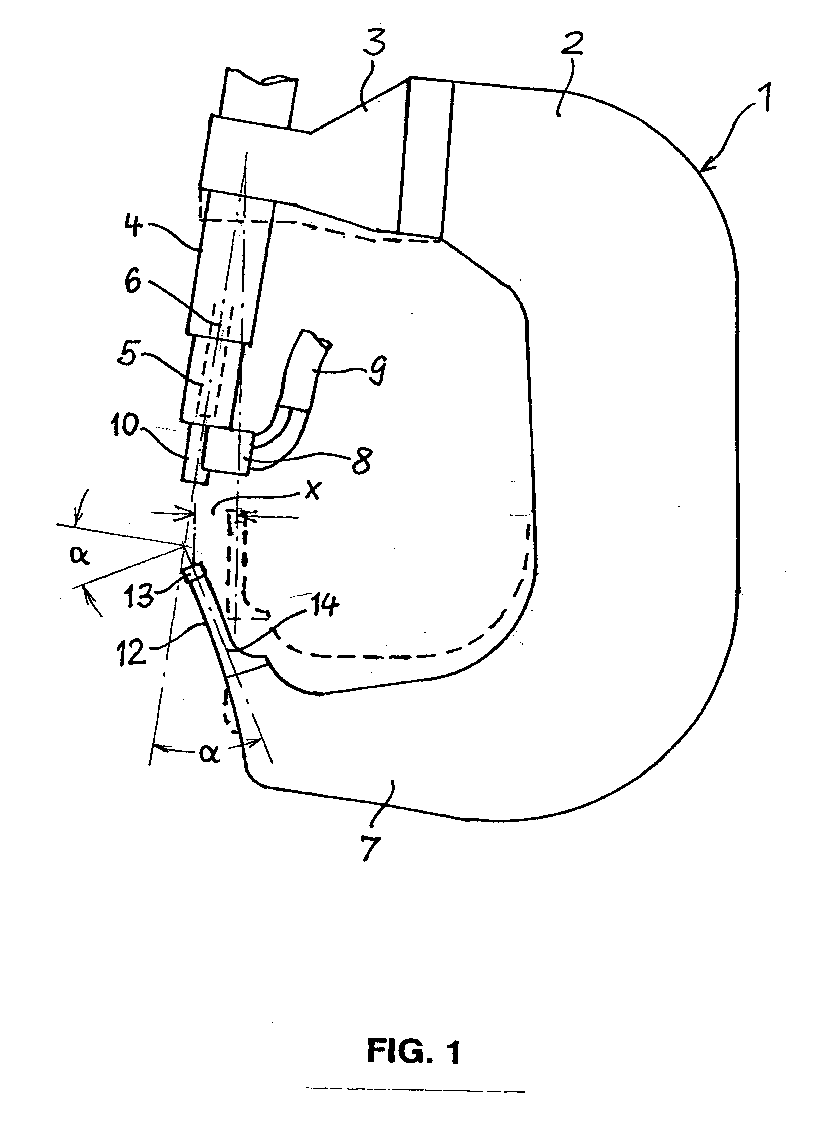
[0021] The present invention addresses problems that occur when a frame is elastically deformed due to loading of the frame in an operation in which fastening members supported on respective arms of the frame engage opposite sides of juxtaposed workpieces. The fastening members may be cooperable tools such as a punch supported on one arm of the frame and a die supported in opposition to the punch on another arm of the frame. The invention is applicable to, but not limited to, riveting, self-piercing riveting, and clinching, for forming joints in sheet metal parts that fasten the parts to one another. By way of example, the invention will be described in its application to self-piercing riveting.

[0022] As shown in FIG. 1, in one embodiment, apparatus of the invention comprises a C-shaped frame 1, which typically is attached to an industrial robot that can move the apparatus into a desired working position. Attached to an arm 2 of the frame 1 (the top arm in FIG. 1) is a holder 3 whi...


PUM

PropertyMeasurementUnit
distanceaaaaaaaaaa
material propertiesaaaaaaaaaa
lengthsaaaaaaaaaa

Abstract

Fastening apparatus comprises a frame having a pair of spaced arms supporting respective cooperable fastening members, loading of the frame during a fastening operation tends to spread the arms and cause variation of a desired predetermined relationship between the fastening members. One of the members is mounted on one arm of the frame by a holder constructed to deform elastically and thereby to provide at least partial compensation for the variation.

Description

CROSS-REFERENCE TO RELATED APPLICATION [0001] This application claims the benefit of German Application DE 10 2005 043 211.5 filed Sep. 9, 2005, incorporated herein by reference. BACKGROUND OF THE INVENTION [0002] This invention relates to a fastening apparatus and method in which load-induced elastic deformation of a supporting frame is at least partially compensated, in order substantially to maintain a desired relationship of cooperable fastening members supported on respective spaced arms of a frame. [0003] Apparatus for forming joints in workpieces, such as sheet metal, by so-called deformational fastening such as riveting, self-piercing riveting, or clinching, is well-known and is widely used in the automotive industry, for example. A fastening device used in such apparatus may comprise punch and die members mounted on respective arms of a C-frame, for example. [0004] The shape of components to be joined to one another may necessitate a variety of positions of a tool (e.g., di...

Claims


Application Information

Patent Timeline
Patent Type & Authority Applications(United States)
IPC IPC(8): B23P11/00
CPCB21J15/10B30B15/047Y10T29/5377Y10T29/5307Y10T29/49833Y10T29/49835Y10T29/49943Y10T29/5343Y10T29/49956
Inventor OPPER, REINHOLDROMERO, RUBEN GUTIERREZMOESER, JOACHIM
Owner NEWFREY
Why Eureka
Try Eureka