Drift scanner for rare cell detection

a scanner and rare cell technology, applied in the field of imaging arts, can solve the problems of difficult to identify each cell individually, difficult to detect affected cells with existing technology, and low concentration of rare cells in blood or other bodily fluids, etc., and achieve the effect of low resolution, high speed and acquired imag

Inactive Publication Date: 2011-01-27
PALO ALTO RES CENT INC
View PDF17 Cites 16 Cited by
  • Summary
  • Abstract
  • Description
  • Claims
  • Application Information

AI Technical Summary

Benefits of technology

A fluorescence microscope for rare cell detection includes a laser beam illumination source for generating a laser beam to illuminate a specimen. A laser beam shaper is configured to generate a flat top (or uniform) laser beam. A time delay integration (TDI) image acquisition system includes a movable stage to hold the specimen, and a bi-directional row shiftable CCD array of a CCD camera system. The movable stage and bi-directional row shiftable CCD array are synchronized to acquire an image of the specimen by TDI. A low resolution image conversion arrangement includes the bi-directional row-shiftable CCD array and a clock which controls operation of the bi-directional row-shiftable CCD array, whereby charge is combined and collected during a readout operation, resulting in a lower resolution, yet high speed, acquired image.

Problems solved by technology

In rare cell studies, a problem arises due to the concentration of rare cells in the blood or other bodily fluids being very low.
However, the produced viral protein exists in very small amounts, and therefore it is difficult to detect affected cells with existing technology.
However, significant obstacles exist to achieving this ideal performance, and in practice a statistically relevant number of cells are not detected due to the cells bunching or clumping together, making it not possible to identify each cell individually.
These concepts do not employ a device such as a fluorescence microscope for the initial pre-scan.

Method used


Image

  • Drift scanner for rare cell detection
  • Drift scanner for rare cell detection
  • Drift scanner for rare cell detection

Examples


Embodiment Construction

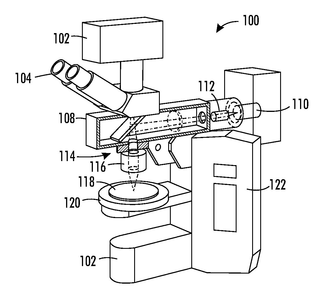
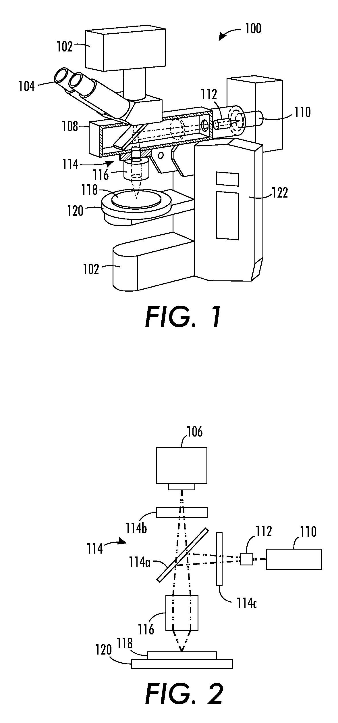
FIG. 1 illustrates a fluorescence microscope rare cell detector 100 having components and operating techniques allowing the microscope to act as a high-speed rare cell detector.

More particularly, fluorescence microscope rare cell detector 100 includes a base 102, which holds an eyepiece 104 that is coupled to a charge-coupled device (CCD) camera system 106. Two illumination sources, including an episcopic illuminator 108 and a light transmission source 110, which may be a laser. A beam shaper 112 is provided within the light source's path, and a filter cube 114 having a dichromatic mirror and filters is positioned to pass light to an objective 116, such that the shaped laser beam illuminates a specimen 118 held on a stage 120. A power source controller arrangement 122 provides power and control circuitry to control output from the illumination sources, as well as control movement of the stage, among other operations.

As mentioned initially, a concept of the present application is to ...


PUM

PropertyMeasurementUnit
areaaaaaaaaaaa
wavelengthsaaaaaaaaaa
fluorescence microscopeaaaaaaaaaa

Abstract

A fluorescence microscope for rare cell detection includes a laser beam illumination source for generating a laser beam to illuminate a specimen. A laser beam shaper is configured to generate a flat top (or uniform) laser beam. A time delay integration (TDI) image acquisition system includes a movable stage to hold the specimen, and a bi-directional row shiftable CCD array of a CCD camera system. The movable stage and bi-directional row shiftable CCD array are synchronized to acquire an image of the specimen by TDI. A low resolution image conversion arrangement includes the bi-directional row-shiftable CCD array and a clock which controls operation of the bi-directional row-shiftable CCD array, whereby charge is combined and collected during a readout operation, resulting in a lower resolution, yet high speed, acquired image.

Description

BACKGROUNDThe present application is directed to the imaging arts, and more particularly to the detection of rare cells in biological applications such as blood smears, biological assays and the like, and will be described with particular reference thereto.With attention to the detection of cells, there are benefits to being able to scan large numbers of cells, such as in the range of 1-10 million cells, or even up to 50 million or more cells at a time. A system which can effectively and quickly scan large numbers of cells would be beneficial in many biological applications, such as an initial or pre-scan of cells to determine the existence of potential rare cells which may be only one in every million or so cells investigated. These rare cells are of interest as they may indicate the existence of various forms of cancer, or certain gene abnormalities, among other biological conditions.In rare cell studies, a problem arises due to the concentration of rare cells in the blood or othe...

Claims


Application Information

Patent Timeline
Patent Type & Authority Applications(United States)
IPC IPC(8): G01N23/00G01T1/16
CPCG01N21/6458G02B21/365G02B21/16
Inventor CURRY, DOUGLAS N.
Owner PALO ALTO RES CENT INC
Why Eureka
Try Eureka