

Electronic device and method for dynamic USB power assignment
- Summary
- Abstract
- Description
- Claims
- Application Information
AI Technical Summary
Benefits of technology
Problems solved by technology
Method used
Image

Examples
Embodiment Construction
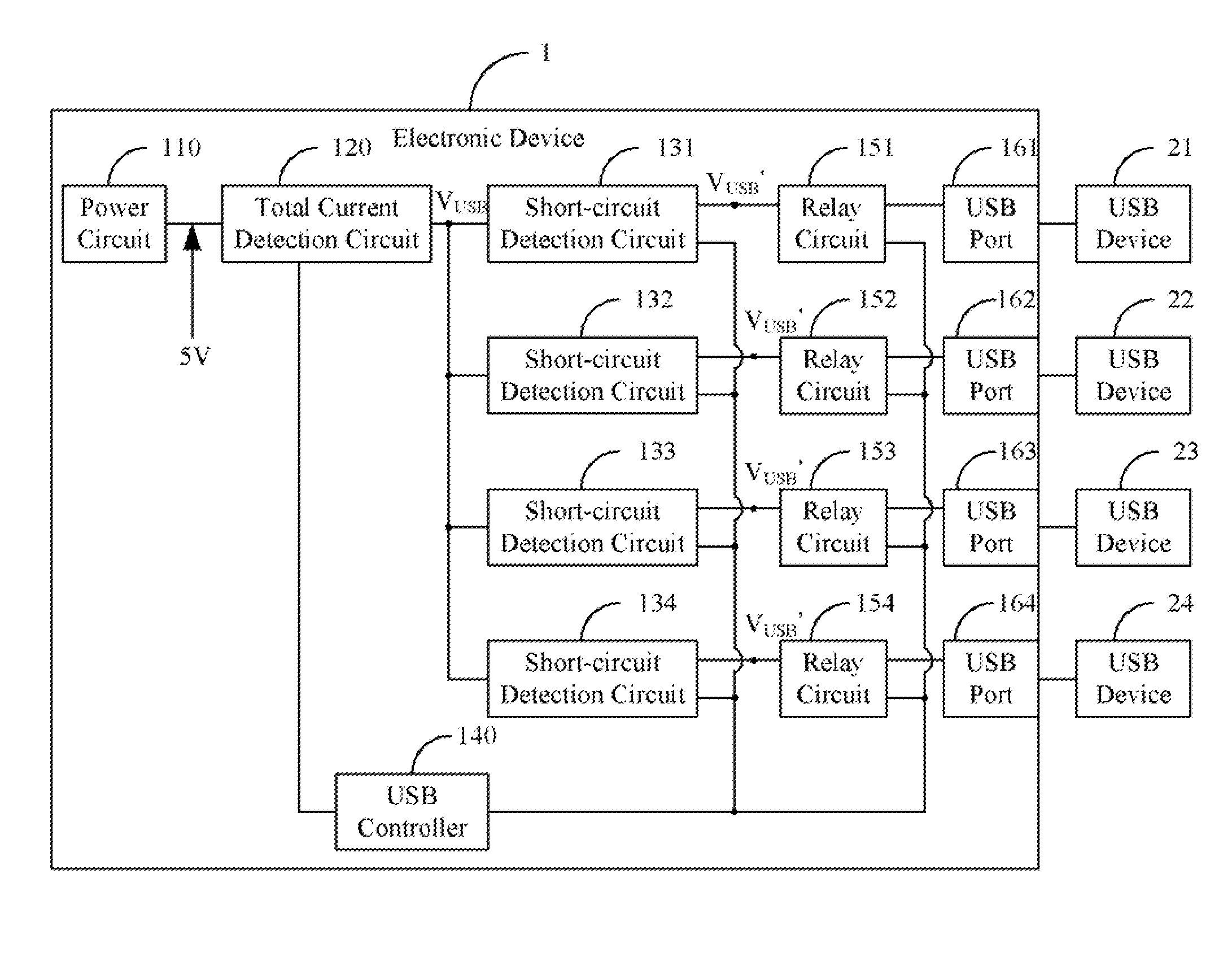
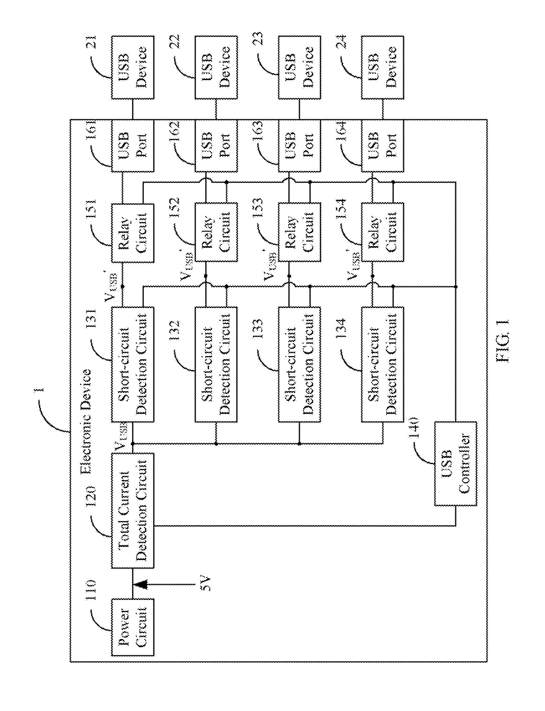
[0011]FIG. 1 is a block diagram of one embodiment of an electronic device 1 for dynamic USB power assignment having no power limits on the USB ports. The electronic device 1 comprises a power circuit 110, a total current detection circuit 120, a plurality of short-circuit detection circuits 131, 132, 133, 134, a USB controller 140, a plurality of relay circuits 151, 152, 153, 154 and a plurality of USB ports 161, 162, 163, 164. The USB ports 161, 162, 163, 164 can be selectively connected to one or more USB devices 21, 22, 23, 24. In the illustrated embodiment, only four USB ports are illustrated, but the disclosure is not limited thereto. Every USB port shown corresponds to one short-circuit detection circuit and one relay circuit.
[0012]The power circuit 110 converts external alternating current (AC) signals to driving voltage signals (such as 5V) to drive the USB ports 161, 162, 163, 164 respectively. The total current detection circuit 120 is connected to the power circuit 110, t...
PUM
 Abstract
Description
Claims
Application Information