Y axis beam positioning system for a PCB drilling machine

a positioning system and beam technology, applied in the direction of printed circuit manufacture, metal working apparatus, manufacturing tools, etc., can solve the problems of limiting the speed and precision of positioning at which the machine can function, adding slight inaccuracies in the positioning and eventual placement of holes in the pcb, and slowing the positioning process, so as to improve the accuracy of positioning. , the effect of shortening the beam settling tim

Inactive Publication Date: 2016-11-22
KOSMOWSKI WOJCIECH B
View PDF40 Cites 0 Cited by
  • Summary
  • Abstract
  • Description
  • Claims
  • Application Information

AI Technical Summary

Benefits of technology

[0008]In accordance with the invention, an object of the present invention is to provide an improved PCB substrate drilling apparatus capable of enhanced Y axis positioning by shorter beam settling times and a tighter tolerance settling window for the Y axis positioning across all points of the beam.
[0009]It is another object of this invention to provide an improved PCB substrate drilling apparatus capable of surpassing the current number of holes drilled in PCB substrates per unit time and remain within operational tolerances.
[0010]It is a further object of this invention to provide a PCB substrate drilling apparatus that increases the precision of the location of the drilled holes.

Problems solved by technology

Since it is this machine that metrology positioning sensors are coupled to, the settling time or lag for the PCB substrate to be positioned within the acceptable ranges of the feedback sensors (prior to the initiation of drilling) is slowed by the effects of the reactionary forces, thus slowing the positioning process and adding slight inaccuracies in the positioning and eventual placement of the holes in the PCB.
Prior art PCB substrate drilling systems rely on the use of a massive, heavy machine base to minimize these reactionary forces coupled with light moving masses of the gantry and attached components as well as an extremely stiff beam, however, these reactionary forces still inherently reside in the machine and serve to limit the speed and precision of positioning at which the machine can function.
This is correct, but within measurable spatial limitations as the beam still has some flex.
These prior art solutions that increase the mass of the machine base (reaction mass) and make the moving masses lighter do not completely address the root cause of the problem—that all parts of the gantry (and beam) are not completely aligned in the Y axis as indicated by the metrology system.

Method used


Image

  • Y axis beam positioning system for a PCB drilling machine
  • Y axis beam positioning system for a PCB drilling machine
  • Y axis beam positioning system for a PCB drilling machine

Examples


Embodiment Construction

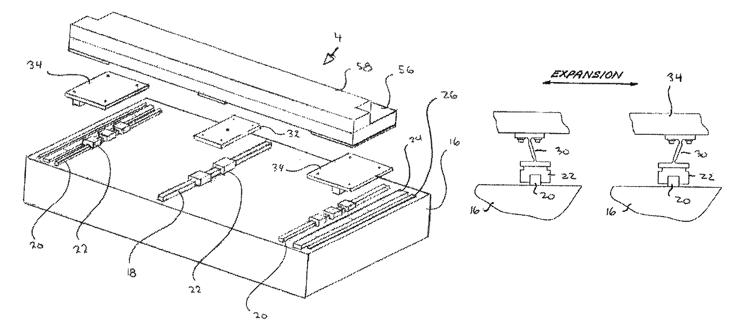
[0021]All discussion of the geometry involved in describing the present invention is made with reference to a three dimensional Cartesian Coordinate System where the z axis is vertical and pointing up (positive up), so that the x and y axes lie on a horizontal plane where the x axis is shown as positive pointing “out of the page” towards the viewer, and the y axis is shown as positive on the right side of the z axis.

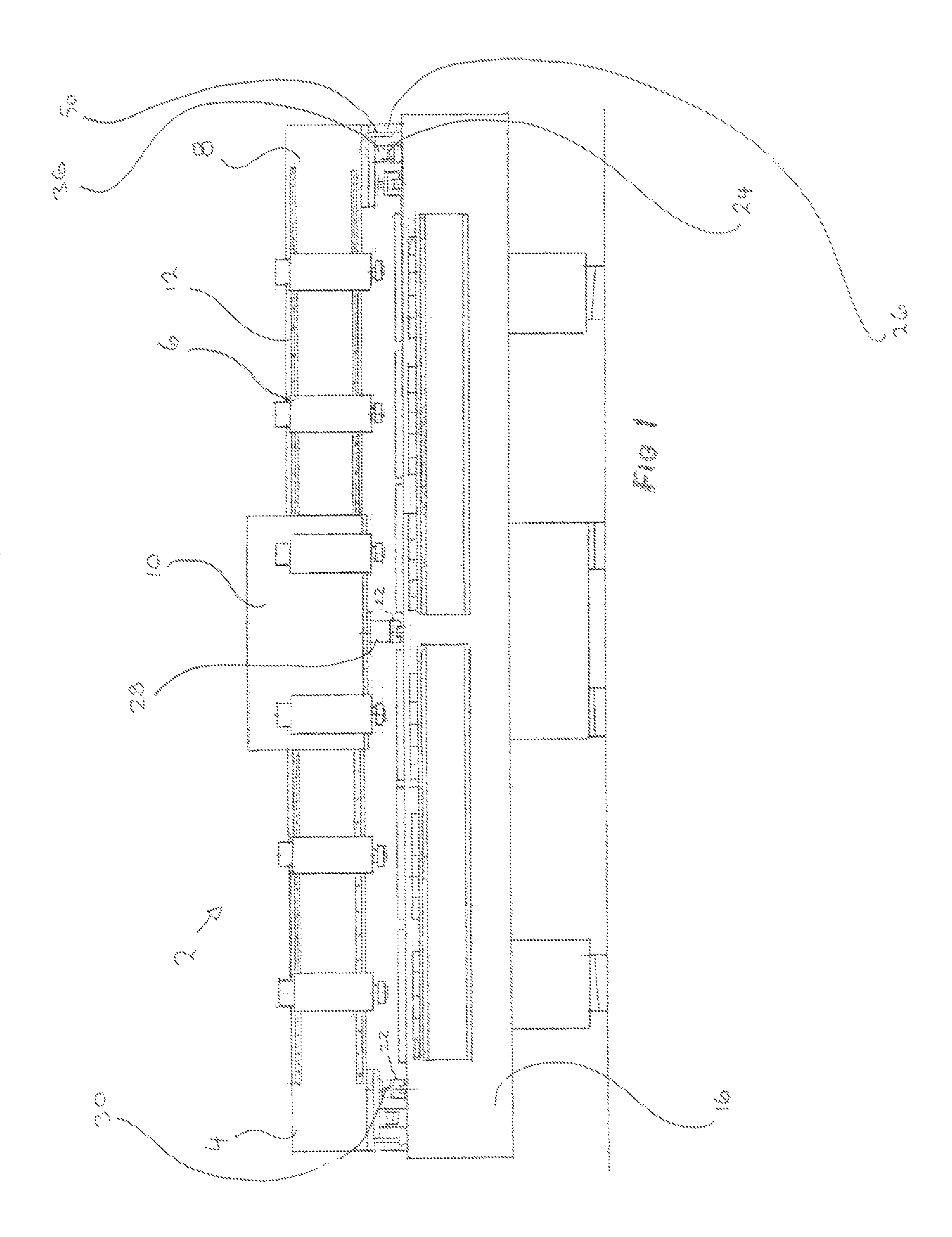
[0022]The term “gantry unit”or “gantry”as used herein is comprised of a linear motor driven stiffened linear member called a “beam”, on the face of which a drill is affixed. The gantry unit also contains the necessary electrical, pneumatic and water supply connections to enable the gantry to move and position in the Y axis as well as for the drills to plunge drill and move and position in the X axis if required. It resides on a set of rails and uses linear positioning sensors to provide feedback signals to the computerized drive system of the linear motor.

[0023]There are...


PUM

PropertyMeasurementUnit
thicknessaaaaaaaaaa
thicknessaaaaaaaaaa
heightaaaaaaaaaa

Abstract

A positioning system for a gantry adapted to move in the horizontal, X-Y plane that utilizes up to 80% less energy to operate than commercial machines, while at the same time decreasing the position settling times by 50%, and achieving this with an “in position window” of 2-3 microns, (a settling window) beating the current industry in position window of 7-12 microns. It accomplishes this through a novel synergistic overall design that utilizes a much lighter and much stiffer moving mass resulting in the moving components having an increased natural frequency. With this system on any style of PCB drilling machine, the drill bit life is extended in two ways: they do not dull as fast and they do not break as often. This is because the small in position window ensures that as the drill bits plunge into the substrate to be drilled (a PCB board) the drill unit sees very little motion in the horizontal plane thus keeping the bits from wandering upon hole initiation and from experiencing excessive horizontal plane sheer forces (side loads) when starting their plunge into the substrate.

Description

[0001]The present invention involves a novel design for an enhanced y axis beam positioning system for a printed circuit board (PCB) substrate drilling machine that greatly increases the speed, and precision with which the machine can position and settle its Y axis beam.BACKGROUND OF THE INVENTION[0002]There is a huge industry developed around the demand to drill multiple, spaced holes (through or non-through) in substrates such as electronic wafers, thin film electronics, organic packaging substrates, glass, silicon wafers, sapphires or the like. These holes or patterned drillings may be used for electrical connections, filtration, cytology, bioassays, chemotaxis, or particle monitoring and have diameters that commonly lie in the micron range. Not only must the holes be identical to each other in diameter but also must be placed at precise locations and with the right geometry with respect to the substrate or adjacent holes.[0003]Generally, such drilling machines see movement in al...

Claims


Application Information

Patent Timeline
Patent Type & Authority Patents(United States)
IPC IPC(8): B23B39/08H05K3/00
CPCH05K3/0047B23B39/08H05K3/0008B23B2270/32H05K2203/0165H05K2203/163H05K2203/166
Inventor KOSMOWSKI, WOJCIECH B.
Owner KOSMOWSKI WOJCIECH B
Why Eureka
Try Eureka