Reducing oscillations in system with foldback current limit when inductive load is connected

a technology of inductive load and foldback current limit, applied in the field of circuitry, can solve the problems of hot swap connection oscillation at the point of pass device size and cost, and achieve the effect of reducing oscillations

Active Publication Date: 2008-03-20
ANALOG DEVICES INT UNLTD
View PDF0 Cites 1 Cited by
  • Summary
  • Abstract
  • Description
  • Claims
  • Application Information

AI Technical Summary

Benefits of technology

[0011]The present disclosure offers a novel system and methodology for driving an inductive load using a pass device for providing hot swap connection to the load. A current limit circuit prevents current supplied to the load from exceeding a current threshold. A foldback c

Problems solved by technology

The current limit foldback technique is used to limit dissipation power, and therefore, size and cost of the pass device.
However, when inductive loads are being connected,

Method used


Image

  • Reducing oscillations in system with foldback current limit when inductive load is connected
  • Reducing oscillations in system with foldback current limit when inductive load is connected
  • Reducing oscillations in system with foldback current limit when inductive load is connected

Examples


Embodiment Construction

[0032]The present disclosure will be made using the example of a PoE system. It will become apparent, however, that the concepts described herein are applicable to any system for driving a connectable inductive load.

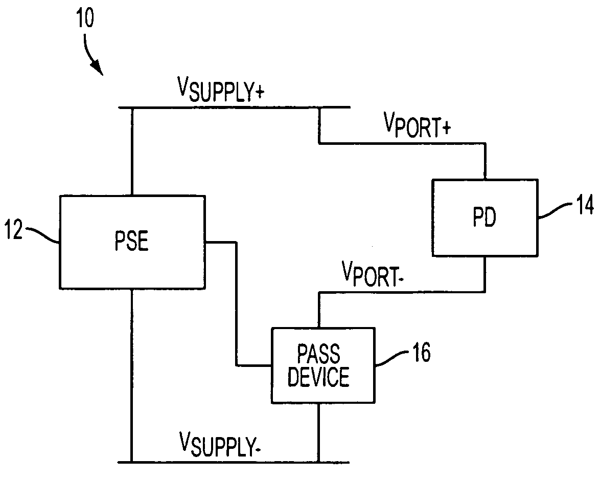
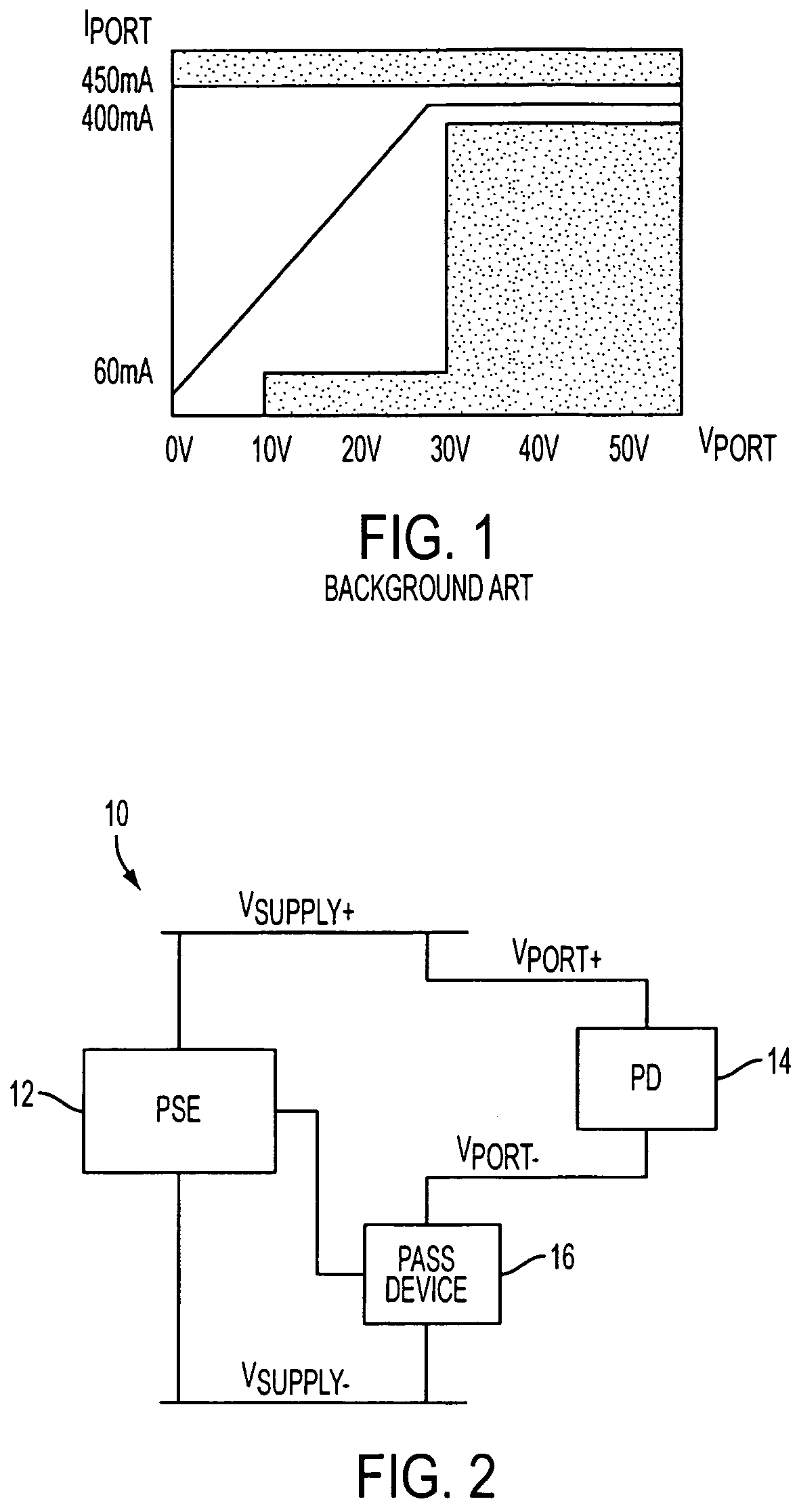
[0033]FIG. 2 schematically illustrates voltages applied in a PoE system 10 between a PSE 12 and a PD 14. In particular, a PSE power supply may include positive terminal Vsupply+ and negative terminal Vsupply−. The PSE 12 may include a pass device 16, such as a power MOSFET, for connecting and disconnecting the PD 14 to and from the PSE 12. The gate of the power MOSFET 16 may be controlled to supply power from the PSE 12 to the PD 14. An output port of the PSE 12 may include positive terminal Vport+ and negative terminal Vport−. The port voltage Vport=Vport+−Vport− provided at the output of the PSE 12 is applied across the PD 14 to deliver the power PPD=(Vport+−Vport−)×Iport, where Iport is a port current. The power Ppass dissipated by the pass device is equal to Vpass×Ip...


PUM


Abstract

System and methodology for driving an inductive load using a pass device for providing hot swap connection to the load. A current limit circuit prevents current supplied to the load from exceeding a current threshold. A foldback circuit controls the current limit circuit to reduce the current threshold when a voltage across the pass device is above a prescribed value. A filter circuit is coupled to the foldback circuit for reducing oscillations when the inductive load is connected to the pass device.

Description

TECHNICAL FIELD[0001]This disclosure relates to power supply systems, and more particularly, to circuitry and methodology for reducing oscillations in a system with a foldback current limit, such as a Power over Ethernet (PoE) system, when an inductive load is being connected.BACKGROUND ART[0002]Electronic systems may have plug-in modules, such as boards or cards, that may be removed from, and inserted into, a live backplane. Each plug-in module usually has a local hot swap controller, ensuring that power is safely applied to that module during both rigorous hot-swap events, and steady-state conditions. The hot swap controller allows a module to be safely inserted to and removed from a live backplane.[0003]For example, a Power over Ethernet (PoE) system uses a hot swap arrangement for connecting or disconnecting a Powered Device (PD) to or from Power Sourcing Equipment (PSE). Traditionally, network devices such as IP phones, wireless LAN access points, personal computers and Web cam...

Claims


Application Information

Patent Timeline
IPC IPC(8): H02H3/08
CPCH04L12/10G06F1/26G05F1/573
Inventor HEATH, JEFFREY LYNN
Owner ANALOG DEVICES INT UNLTD
Why Eureka
Try Eureka