DC/DC converter

a dc/dc converter and current limiter technology, applied in the direction of electric variable regulation, process and machine control, instruments, etc., can solve the problems of shortening the operating life of equipment such as personal computers, affecting the portability of equipment, and difficulty in a single dc/dc converter to supply large curren

Inactive Publication Date: 2005-07-07
ROHM CO LTD
View PDF5 Cites 2 Cited by
  • Summary
  • Abstract
  • Description
  • Claims
  • Application Information

AI Technical Summary

Benefits of technology

[0011] To achieve the above object, according to the present invention, a multiphase DC / DC converter is provided with: a plurality of DC / DC converters whose outputs are connected in parallel with one another; and an overcurrent detection / prevention circuit for detecting and adding together the output currents of the plurality of DC / DC converters and controlling the plurality of DC / DC converters individually so that the sum of the output currents does not exceed a predetermined level of current.
[0012] Alternatively, according to the present invention, a multiphase DC / DC converter is provided with: a plurality of DC / DC converters whose outputs are connected in parallel with one another and which each have an overcurrent detection circuit so as to limit the output current thereof according to the output of the overcurrent detection circuit so that the output currents of the individual DC / DC converters do not exceed predetermined currents; and an overcurrent detection / prevention circuit for detecting and adding together the individual output currents and controlling the plurality of DC / DC converters individually so that the sum of the output currents does not exceed a predetermined level of current.
[0014] More specifically, the overcurrent detection / prevention circuit is provided with: a plurality of amplifiers for amplifying voltages obtained through current-to-voltage conversion of the individual output currents and outputting the amplified voltages; a plurality of input resistors having one ends thereof connected respectively to the output terminals of the amplifiers and having the other ends thereof connected together at a common node so that currents proportional to the individual output currents flow through the input resistors; an adder having the inverting input terminal thereof connected to the common node of the plurality of resistors and outputting, at the output terminal thereof, a voltage proportional to the sum of input currents individually flowing through the plurality of input resistors; and a comparator for comparing the output voltage of the adder with a predetermined reference voltage. Here, when the output voltage of the adder, which is proportional to the sum of the individual output currents and which is fed to the comparator, is higher than the predetermined reference voltage, the comparator feeds the individual DC / DC converters with a signal for limiting currents to control the individual DC / DC converters so that the sum of the individual output currents does not exceed a predetermined level of current.

Problems solved by technology

Such personal computers are increasingly operated from built-in batteries rather than from commercially distributed power, and it is difficult for a single DC / DC converter to supply large current as mentioned above.
Moreover, to eliminate ripples appearing in the supply voltage, a high-capacitance capacitor or a combination of many capacitors is required, which hampers miniaturization of equipment such as personal computers in which portability matters.
This overloads the circuit elements provided on the primary side of the converters or the battery, eventually damaging them or shortening their operating lives.
This overloads the load, causing similar problems on this side, too.
On the other hand, when the current limit of one of the converters happens to fall below the prescribed current, overcurrent prevention may be invoked needlessly.
This momentarily increases the other converters' share of the load current, adversely affecting the circuit elements provided on the secondary side of the converters which have to temporarily share the load, and thereafter invokes overcurrent protection in all of the converters, leading to an unnecessary shut-off of supply power.

Method used


Image

  • DC/DC converter
  • DC/DC converter
  • DC/DC converter

Examples


Embodiment Construction

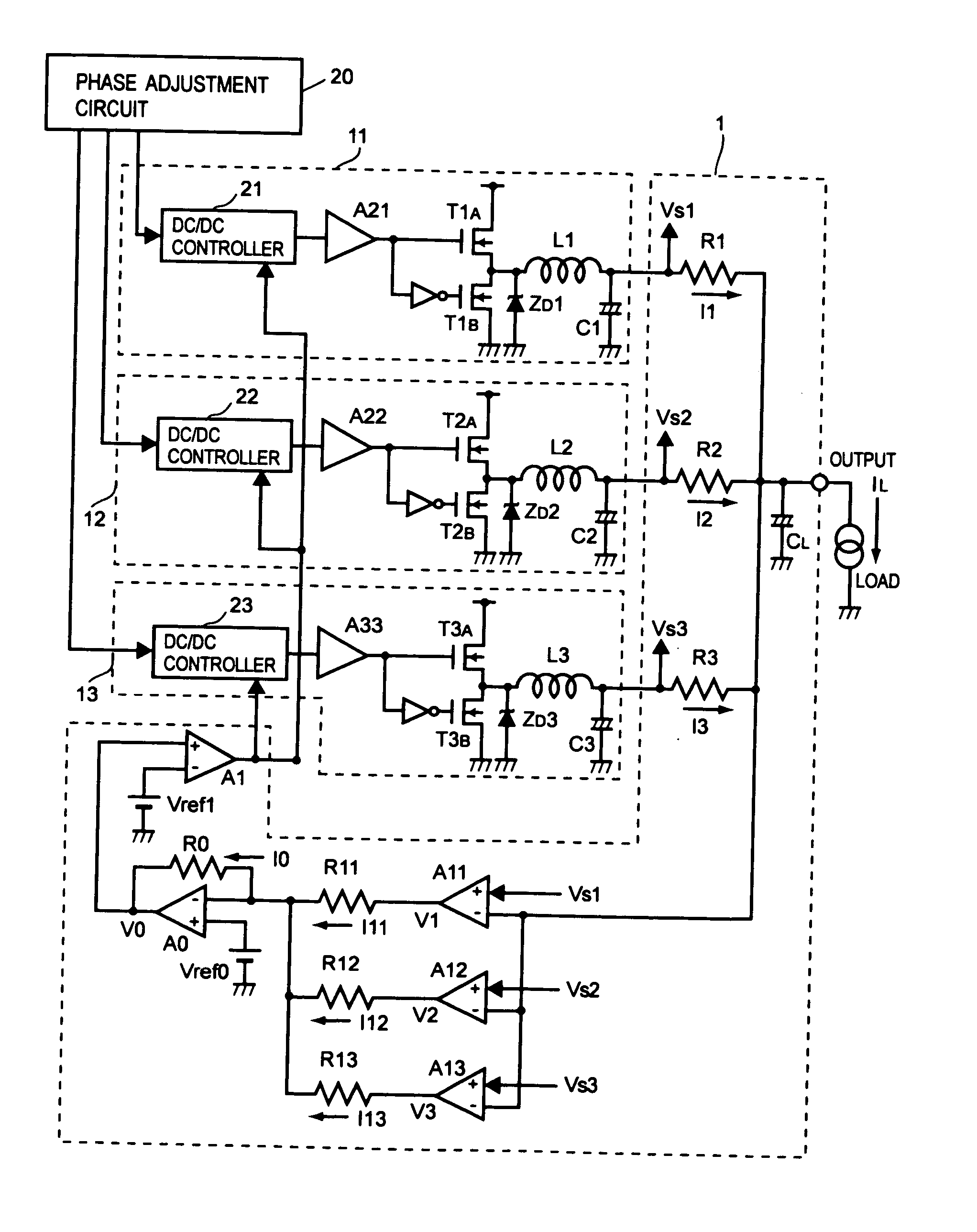
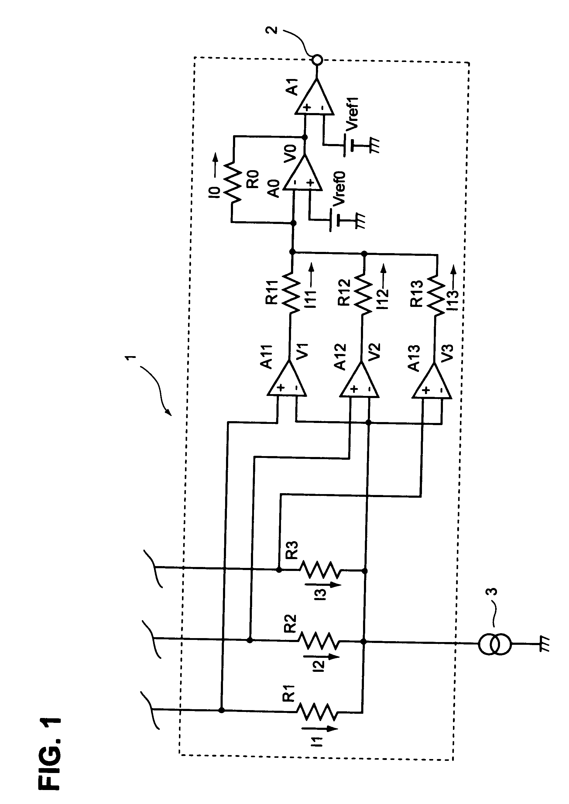
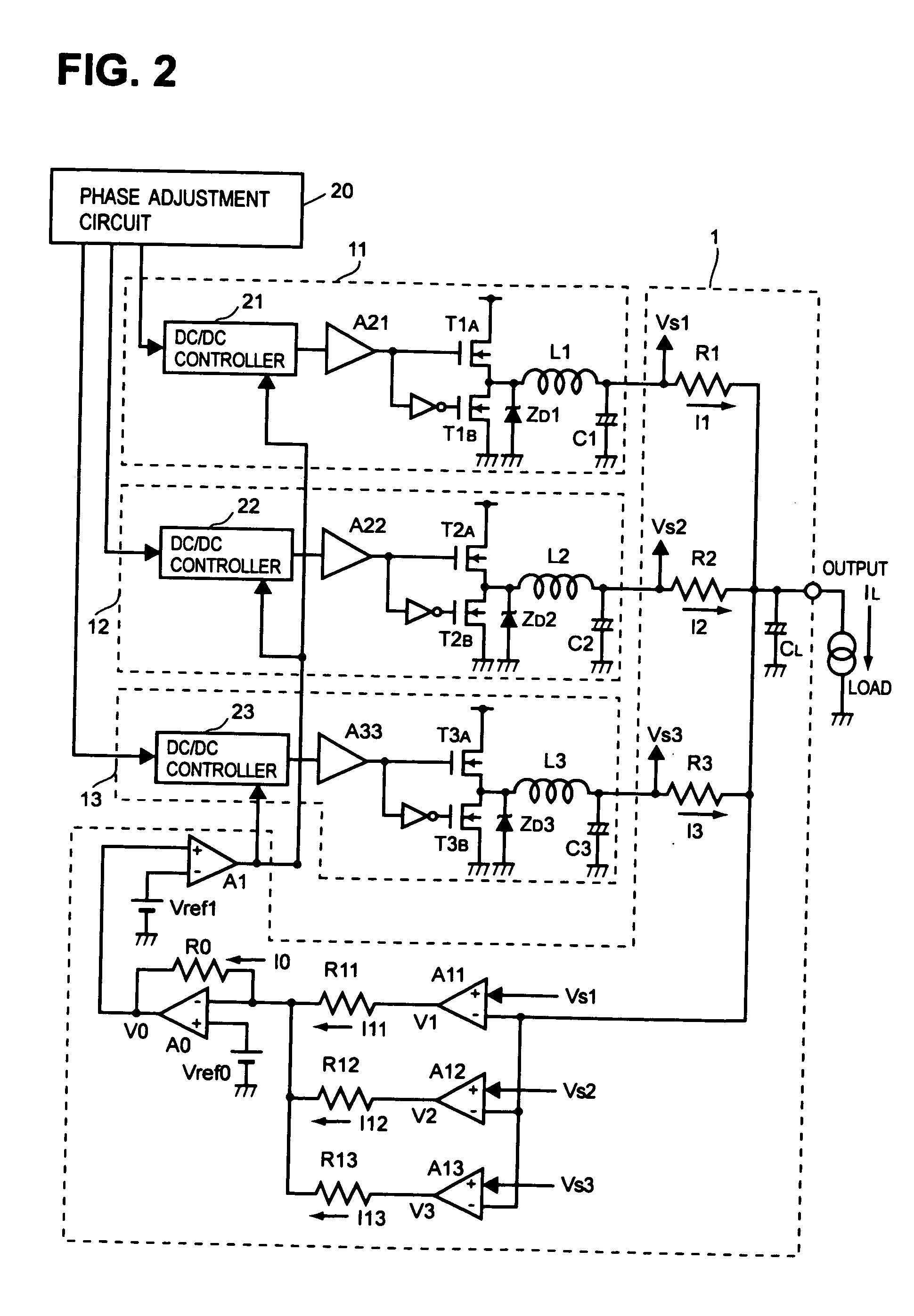
[0021] Hereinafter, embodiments of the present invention will be described with reference to the drawings. FIG. 1 shows, as one embodiment of the invention, an overcurrent detection / prevention circuit for detecting the sum of load currents.

[0022] The overcurrent detection / prevention circuit 1 shown in FIG. 1 has current detection resistors R1, R2, and R3 connected respectively in the output paths of three unillustrated DC / DC converters, and the three output paths are connected, in parallel with one another, to a load 3. The terminal of the current detection resistor R1 opposite to the load is connected to the non-inverting input terminal (+) of an amplifier A11, the terminal of the current detection resistor R2 opposite to the load is connected to the non-inverting input terminal of an amplifier A12, and the terminal of the current detection resistor R3 opposite to the load is connected to the non-inverting input terminal of an amplifier A13. The node at which the current detection...


PUM


Abstract

In a multiphase DC / DC converter having a plurality of DC / DC converters, to prevent faults in the circuit and the circuit elements constituting it even when the balance of current limiting operation among the individual DC / DC converters is disturbed due to individual and temperature-related variations in the characteristics of the circuit elements, the output currents of the individual DC / DC converters are detected and added together, and are limited individually so that their sum does not exceed a predetermined level of current.

Description

BACKGROUND OF THE INVENTION [0001] 1. Field of the Invention [0002] The present invention relates to a current limiter circuit in a multiphase DC / DC converter used as a power supply in a personal computer or the like. [0003] 2. Description of the Prior Art [0004] As IT (information technology) equipment evolves in functionality, processing speed, and scale, it requires more and more current from power supply circuits. In particular in personal computers, with ever increasing clock speeds of CPUs and with diversification of peripheral devices that are supplied with power from personal computers, it is nowadays common that a load current of the order of a few tens of A to over 100 A is required. [0005] Such personal computers are increasingly operated from built-in batteries rather than from commercially distributed power, and it is difficult for a single DC / DC converter to supply large current as mentioned above. Moreover, to eliminate ripples appearing in the supply voltage, a high-...

Claims


Application Information

Patent Timeline
Patent Type & Authority Applications(United States)
IPC IPC(8): H02M3/155H02M3/158
CPCH02M3/1584
Inventor TAKEMURA, KOUMEMOTO, KIYOTAKA
Owner ROHM CO LTD
Why Eureka
Try Eureka