Method for Regulating the Angular Velocity of Printing Cylinders

a technology of angular velocity and printing cylinder, which is applied in the direction of speed regulation of multiple dynamo-electric motors, dynamo-electric machines, and dynamo-motor starters. it can solve the problems of poor superposition of images printed by the various printing units in the direction, laborious and inflexible mounting operation, and varies the feed coefficient of blankets

Inactive Publication Date: 2011-01-27
GOSS INT MONTATAIRE
View PDF6 Cites 3 Cited by
  • Summary
  • Abstract
  • Description
  • Claims
  • Application Information

AI Technical Summary

Benefits of technology

[0025]When the two cylinders correspond to two cooperating blanket cylinders from the same printing unit, the difference in angular velocity enables the difference between the feed coefficients of the two blankets to be compensated for in order to equalize the motor torques to be provided.
[0026]When the two cylinders correspond to two blanket cylinders from two different printing units, the difference in angular velocity enables the tension of the paper web between the two printing units to be maintained at a desired value.

Problems solved by technology

Another problem of offset printing arises in offset printing machines that print on a web of paper.
This leads to poor superposition of the images printed by the various printing units in the direction perpendicular to the travel of the paper web.
However, the stipulation of a precise order for mounting the blankets renders the mounting operation tedious, laborious and inflexible.
Furthermore, the feed coefficient of a blanket varies in the course of its use, for example owing to the deterioration in the microbubbles contained in its compressible layer, or owing to the continuous action of the solvents, inks and cleaning products on the blanket.
That makes it difficult to change a single blanket which has been destroyed accidentally.

Method used


Image

  • Method for Regulating the Angular Velocity of Printing Cylinders
  • Method for Regulating the Angular Velocity of Printing Cylinders
  • Method for Regulating the Angular Velocity of Printing Cylinders

Examples


first embodiment

Optimization of the Cleaning of the Blanket

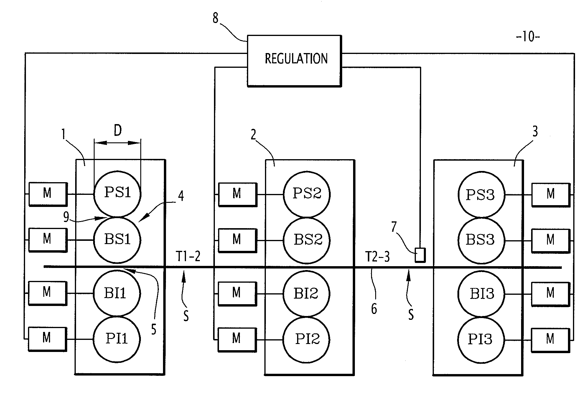
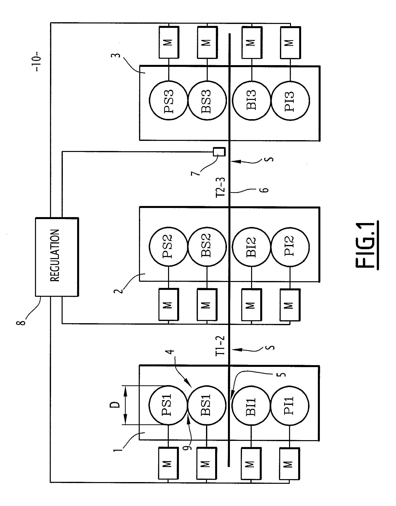
[0071]In a first embodiment, the first and the second cylinder for which a difference in angular velocity is generated are, within the same printing unit, a blanket cylinder and its associated plate cylinder, respectively. For example, they may be the cylinders bs1 and ps1 of the printing unit 1, or the cylinders bi3 and pi3 of the printing unit 3.

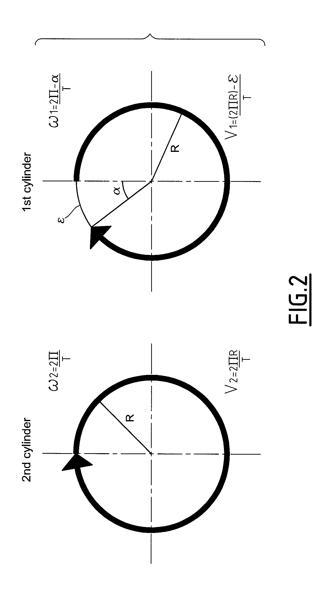
[0072]An object here is to obtain efficient cleaning of the blanket of the blanket cylinder. To that end, the adaptation value alpha α (or Epsilon ε) is set at a value sufficiently high to ensure efficient cleaning of the blanket. At the same time, the value of alpha a (or of Epsilon) is set at a value sufficiently low not to cause interference with the printing quality. Experiments have shown that the preferred range, in particular for cylinders having a diameter of, for example, approximately 400 mm, for alpha extends from 2.5×10⁻⁶ to 2.5×10⁻⁵ radians, which corresponds to an Epsilon range of fr...

second embodiment

Ensuring Correct Superposition of the Printed Images

[0075]In this embodiment, the first cylinder corresponds to a blanket cylinder of a first printing unit, and the second cylinder corresponds to a blanket cylinder of a second printing unit. The first cylinder carries a first blanket with a feed coefficient C1, while the second cylinder carries a second blanket with a feed coefficient C2.

[0076]The object of this embodiment is to keep the tension prevailing in a segment S of paper web 6 located between two printing units at a desired value in order to ensure correct superposition of the images printed by each printing unit. To that end, the value of alpha (or of Epsilon) is chosen to compensate for the difference C1−C2 between the feed coefficients of the two blankets.

[0077]For example, if the feed coefficient of one blanket gives an exact figure for the deviation of the paper feed rate for one rotation of the cylinder relative to the theoretical feed rate, then Epsilon=C1−C2.

[0078]W...

third embodiment

Permitting the Use of Less Powerful Motors

[0083]In this embodiment, the first and the second cylinder correspond to the upper blanket cylinder and to the lower blanket cylinder, respectively, of the same printing unit. The first cylinder carries a first blanket with a feed coefficient C1, while the second cylinder carries a second blanket with a feed coefficient C2. Those cylinders may be, for example, the cylinders bs2 and bit of the printing unit 2, or the cylinders bs3 and bi3 of the printing unit 3.

[0084]An object here is to optimize the distribution of the motor torques within the same printing unit. To that end, the value of Epsilon is chosen to compensate for the difference C1−C2 between the feed coefficients of the two blankets.

[0085]For example, if the feed coefficient of one blanket represents exactly the deviation of the paper feed rate for one rotation of the cylinder relative to the theoretical feed rate, then Epsilon=C1−C2.

[0086]With the resultant slight difference in ...


PUM


Abstract

A method for regulating a first printing unit is provided. The first printing unit includes a plate cylinder, a first blanket cylinder carrying a tubular blanket and an impression cylinder. The first blanket cylinder defines a region of contact with the plate cylinder. The impression cylinder defines a region of counter-pressure with the first blanket cylinder. The method includes when the first printing unit is printing, a regulating step of a duration greater than or equal to six minutes in respect of the angular printing velocity ω1 of the first blanket cylinder relative to the angular printing velocity ω2 of the plate cylinder so that, for at least part of the duration of the regulating step, the ratio ω1/ω2 of the angular velocities is different from the ratio D2/D 1 between the diameter D2 of the plate cylinder and the diameter D1 of the first blanket cylinder in order to define a difference in velocity Δω=ω1−ω2×D2/D1, any difference in velocity Δωbeing of the same sign throughout the entire duration of the regulating step.

Description

[0001]This claims the benefit of French Patent Application No. 09 54890, filed on Jul. 15, 2009 and hereby incorporated by reference herein.[0002]The present invention relates to a method for regulating the angular velocity of printing cylinders of printing units. The present invention is applicable in particular to rotary web offset presses.BACKGROUND OF THE INVENTION[0003]A method for regulating the register of a printing unit is known from the document EP 1 048 461 B1. Another document EP 1 364 780 A2 describes a method in which, during a maintenance phase, a plate cylinder is driven at a rate of rotation different from that of an associated blanket cylinder.[0004]One of the known problems of the offset printing process is the soiling of the blankets, which brings about a reduction in the surface area of the printed dots, a phenomenon which is often referred to as “dot vanishing”. The blankets are soiled by the deposition, at the non-printing sites of the blankets, of a small amo...

Claims


Application Information

Patent Timeline
Patent Type & Authority Applications(United States)
IPC IPC(8): H02P5/52
CPCB41F7/12B41P2213/734B41F13/0045
Inventor LEPELTIER, PATRICK
Owner GOSS INT MONTATAIRE
Why Eureka
Try Eureka