Stereoscopic imaging apparatus and stereoscopic imaging method

a stereoscopic imaging and stereoscopic imaging technology, applied in electrical devices, television system details, television systems, etc., can solve the problems of affecting the stereoscopic image quality, the stereoscopic view is not possible, and the three-dimensional effect of the image may be lost, etc., to achieve convenient stereoscopic view, avoid the effect of focus position deviation and compact size of the apparatus

Inactive Publication Date: 2011-01-27
FUJIFILM CORP
View PDF4 Cites 46 Cited by
  • Summary
  • Abstract
  • Description
  • Claims
  • Application Information

AI Technical Summary

Benefits of technology

[0009]In the configuration of Japanese Patent Application Laid-Open No. 8-194274, a mechanism configured to adjust the convergence angle is essential, and such a mechanism is complicated by any means, resulting in a large apparatus size and a high cost.
[0010]The presently disclosed subject matter has been made in view of the circumstances, and an object of the presently disclosed subject matter is to provide a stereoscopic imaging apparatus and a stereoscopic imaging method capable of obtaining a stereoscopic image in which deviation of focus position is prevented, by which stereoscopic view is easily obtained, and eyes of a viewer hardly get tired, and capable of making the size of apparatus compact.
[0011]To attain the object, a first aspect of the presently disclosed subject matter provides a stereoscopic imaging apparatus including: a first imaging device configured to include a first imaging optical system with a first focus lens and to image a subject to generate a first image; a second imaging device configured to include a second imaging optical system with a second focus lens and to image the subject to generate a second image; a lens driving device configured to move the first and second focus lenses along a first optical axis of the first imaging optical system and a second optical axis of the second imaging optical system, respectively; a focus position detection device configured to detect a first focus position in an imaging space of the first focus lens and a second focus position in an imaging space of the second focus lens; a stereoscopic view possible range calculation device configured to calculate a stereoscopic view possible range where a parallax amount of the first imaging device and the second imaging device is within an acceptable range; a focus position determination device configured to determine whether the focus positions are within the stereoscopic view possible range; and a focus control device configured to cause the first focus lens and the second focus lens to focus on one focus position of the first focus position and the second focus position, said one focus position determined to be within the stereoscopic view possible range. According to the aspect, the first and second focus lenses focus on the focus position in the stereoscopic view possible range even if the subject is not at the intersection (cross point) of the optical axes of the imaging optical systems and if the focus search is performed by the imaging devices by setting the focus area at the center of the angle of view. Therefore, a stereoscopic image can be obtained in which deviation of focus position is prevented, stereoscopic view is easy, the eyes do not get tired easily, and the three dimensional effect is excellent. Moreover, since a mechanism for adjusting the convergence angle is not necessary, an inexpensive stereoscopic imaging apparatus with compact apparatus size can be provided.
[0013]A second aspect of the presently disclosed subject matter provides a stereoscopic imaging apparatus including: a first imaging device configured to include a first imaging optical system with a first focus lens and to image a subject to generate a first image; a second imaging device configured to include a second imaging optical system with a second focus lens and to image the subject to generate a second image; a lens driving device configured to move the first and second focus lenses along a first optical axis of the first imaging optical system and a second optical axis of the second imaging optical system, respectively; a focus position detection device configured to detect a first focus position in an imaging space of the first focus lens and a second focus position in an imaging space of the second focus lens; a field depth calculation device configured to calculate depths of field of the imaging devices; a focus position determination device configured to determine whether both the first focus position and the second focus position are included in the depths of field of the imaging devices; and a focus control device configured to cause the first focus lens and the second focus lens to focus on one of the focus positions detected by the imaging device, the depth of field of which includes both the first focus position and the second focus position. According to the aspect, the first and second focus lenses focus on one of the focus positions detected by the imaging device including both focus positions in the depth of field even if the subject is not at the intersection (cross point) of the optical axes of the imaging optical systems and if the focus search is performed by the imaging devices by setting the focus area at the center of the angle of view. Therefore, an excellent stereoscopic image can be obtained in which deviation of focus position is prevented, stereoscopic view is easy, and the eyes do not get tired easily. Moreover, since a mechanism for adjusting the convergence angle is not necessary, an inexpensive stereoscopic imaging apparatus having a compact apparatus size can be provided.
[0014]A third aspect of the presently disclosed subject matter provides a stereoscopic imaging apparatus including: a first imaging device configured to include a first imaging optical system with a first focus lens and to image a subject to generate a first image; a second imaging device configured to include a second imaging optical system with a second focus lens and to image the subject to generate a second image; a lens driving device configured to move the first and second focus lenses along a first optical axis of the first imaging optical system and a second optical axis of the second imaging optical system, respectively; a focus position detection device configured to detect a first focus position in an imaging space of the first focus lens and a second focus position in an imaging space of the second focus lens; a parallax amount calculation device configured to calculate a parallax amount of the first imaging device and the second imaging device for each of the focus positions; a focus position determination device configured to determine the focus position with the smaller parallax amount from among the first focus position and the second focus position; and a focus control device configured to cause the first focus lens and the second focus lens to focus on the focus position determined by the focus position determination device to have the smaller parallax amount. According to the aspect, the first and second focus lenses focus on the focus position with the smaller parallax amount even if the subject is not at the intersection (cross point) of the optical axes of the imaging optical systems and if the focus search is performed by the imaging devices by setting the focus area at the center of the angle of view. Therefore, an excellent stereoscopic image can be obtained in which deviation of focus position is prevented, stereoscopic view is easy, and the eyes do not get tired. Moreover, since a mechanism for adjusting the convergence angle is not necessary, an inexpensive stereoscopic imaging apparatus having a compact apparatus size can be provided.
[0027]According to the presently disclosed subject matter, a stereoscopic image can be obtained, in which deviation of focus position is prevented, by which stereoscopic view is easily obtained, and the eyes of the viewer hardly get tired, and the size of apparatus can be made compact.

Problems solved by technology

The three dimensional effect of image may be lost due to the deviation of focus position.
However, the coincided focus positions may be out of a stereoscopic view possible range, and an appropriate stereoscopic image may not be obtained.
In the configuration of Japanese Patent Application Laid-Open No. 8-194274, a mechanism configured to adjust the convergence angle is essential, and such a mechanism is complicated by any means, resulting in a large apparatus size and a high cost.

Method used


Image

  • Stereoscopic imaging apparatus and stereoscopic imaging method
  • Stereoscopic imaging apparatus and stereoscopic imaging method
  • Stereoscopic imaging apparatus and stereoscopic imaging method

Examples


first embodiment

[0094]FIG. 5 is a block diagram illustrating an internal configuration of the digital camera 101 according to a first embodiment. The elements illustrated in FIGS. 1 and 2 are designated with the same reference numerals, and the description of the already described content will not be repeated.

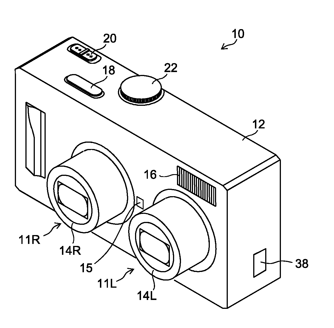
[0095]As illustrated in FIG. 5, the digital camera 101 of the present embodiment is configured to be able to acquire an image signal from each of the two imaging systems 11L and 11R. The digital camera 101 includes a stereoscopic view possible range calculation unit 42, a focus position determination unit 48, a CPU 110, a time keeping (measuring) unit 111, an operation unit 112, a ROM (read only memory) 116, a flash ROM 118, an SDRAM (synchronous dynamic random access memory) 120, a VRAM (video RAM) 122 (image display memory), zoom lens control units 124 (124L and 124R), focus lens control units 126 (126L and 126R), aperture control units (iris control units) 128 (128L and 128R), imaging eleme...

second embodiment

[0151]FIG. 12 is a block diagram illustrating an internal configuration of a digital camera 102 according to a second embodiment. The same elements as in the digital camera 101 of the first embodiment illustrated in FIG. 5 are designated with the same reference numerals, and only items different from the first embodiment will be described.

[0152]A focus position determination unit 58 of the present embodiment determines whether the focus positions P1 and P2 are within the stereoscopic view possible range.

[0153]Although depicted separately from the CPU 110 in FIG. 12, the stereoscopic view possible range calculation unit 42 and the focus position determination unit 58 may be constituted by the CPU 110.

[0154]FIGS. 13A and 13B are flowcharts illustrating an example of a flow of a stereoscopic imaging control process according to the second embodiment. The CPU 110 of FIG. 12 executes the process in accordance with a program.

[0155]An example will be described in which stereoscopic view im...

third embodiment

[0164]FIG. 16 is a block diagram illustrating an internal configuration of a digital camera 103 according to a third embodiment. The same elements as in the digital camera 101 according to the first embodiment illustrated in FIG. 5 are designated with the same reference numerals, and only items different from the first embodiment will be described.

[0165]A field depth calculation unit 64 calculates depths of field (field depth) of the imaging systems 11L and 11R.

[0166]A focus position determination unit 68 of the present embodiment determines whether both the left imaging system focus position P1 and the right imaging system focus position P2 are included in the depths of field of the imaging systems 11L and 11R.

[0167]Although depicted separately from the CPU 110 in FIG. 16, the field depth calculation unit 64 and the focus position determination unit 68 may be constituted by the CPU 110.

[0168]FIGS. 17A and 17B are flowcharts illustrating an example of a flow of a stereoscopic imagin...


PUM


Abstract

A stereoscopic imaging method using: first and second imaging devices including first and second imaging optical systems with first and second focus lenses and imaging a subject to generate first and second images; and a lens driving device configured to move the first and second focus lenses along the first and second optical axes of the first and second imaging optical systems, respectively, the method includes: moving the focus lenses to detect first and second focus positions in an imaging space of the first and second focus lenses, respectively; calculating a stereoscopic view possible range where a parallax amount of the first and second imaging device is within an acceptable range; determining whether the focus positions are between an intersection of the optical axes and a near point of the stereoscopic view possible range; and causing the lens driving device to focus the first and second focus lens on the determined focus position.

Description

BACKGROUND OF THE INVENTION[0001]1. Field of the Invention[0002]The presently disclosed subject matter relates to a stereoscopic imaging apparatus including a plurality of imaging devices and a stereoscopic imaging method using a plurality of imaging devices, and particularly, to a stereoscopic imaging apparatus and a stereoscopic imaging method configured to obtain a stereoscopic image in which displacement (deviation) of focus positions of the imaging devices is prevented (decreased or minimized), by which stereoscopic view is easily obtained, and eyes of a viewer hardly get tired.[0003]2. Description of the Related Art[0004]There is a known stereoscopic imaging apparatus including: a left imaging system that includes a left imaging optical system with a focus lens and that images a subject to generate a photographic image for a left eye (a left eye image); and a right imaging system that includes a right imaging optical system with a focus lens and that images the subject to gene...

Claims


Application Information

Patent Timeline
Patent Type & Authority Applications(United States)
IPC IPC(8): H04N13/02
CPCH04N5/23212H04N13/0296H04N13/0239H04N13/296H04N13/239H04N23/673H04N23/632
Inventor PAN, YI
Owner FUJIFILM CORP
Why Eureka
Try Eureka