Ceiling-mounted loudspeaker enclosure

a loudspeaker and enclosure technology, applied in the direction of transducer details, electrical transducers, electrical apparatus, etc., can solve the problems of coaxially mounted tweeters suffering from the lack of baffles, the level of output power has become a challenge for ceiling loudspeaker designers, and the efficiency of speakers

Active Publication Date: 2011-01-27
POLK AUDIO LLC
View PDF25 Cites 20 Cited by
  • Summary
  • Abstract
  • Description
  • Claims
  • Application Information

AI Technical Summary

Benefits of technology

[0009]The foregoing slanted mounting configuration provides a speaker assembly having a circular cross-section but an oval speaker that has an enhanced radiating area yet will fit through a smaller hole than would be possible with a circular speaker of similar radiating area. It has been found that the in-ceiling loudspeaker assembly of the present invention provides the bass performance of a standard speaker that is one size larger than would be expected from a loudspeaker having the circular diameter of the enclosure; for example, it will provide the bass frequency output of a standard 6.5″ system in a 5.25″ ceiling hole.
[0010]In accordance with another aspect of the present invention, the in-ceiling speaker assembly of the present invention also overcomes the problems of coaxially-mounted midrange and high-range speakers in a small speaker system. As described above, the low frequency driver (woofer) unit is located in the rear of the system, or at the top of the tubular enclosure, and the speaker module with its midrange and tweeter is located at the bottom end of the enclosure, in front of the woofer. The speaker module includes a face plate that incorporates ports transmitting the sound from the woofer into a listening space in front of the speaker assembly; i.e., below the ceiling, but in accordance with the invention this face plate also serves as a baffle plate for mounting tweeter and midrange drivers within the enclosure. Since the ports take up only a portion of the surface of the baffle, the tweeter and midrange driver outputs suffer much less from the diffraction and reflection than occurs in a comparable two-way, in-ceiling speaker system. The dispersion in the midrange and high frequencies are much better as a result.

Problems solved by technology

However, making a loudspeaker smaller generally involves a trade off in performance, usually involving the loss of bass frequencies, a reduction in speaker efficiency, or a combination of both, and as the size of the hole on the ceiling is reduced, the installation of an acoustic driver large enough to produce the desired level of output power has become a challenge for ceiling loudspeaker designers.
This presents two problems.
The first is that a coaxially mounted tweeter suffers from the lack of a baffle, for if it is mounted on a bridge it is left hanging above the mid-bass driver.
In such a structure, sound radiates from the tweeter to the mid-bass driver and then back out, causing frequency response anomalies in the far field.
The second problem is that the mid-bass driver becomes “beamy” at the top of its working range; that is, its sound dispersion pattern is narrow so that as a listener moves off-axis from the driver, less upper midrange sound is heard.
The tweeter cannot compensate for this because the low end of its range has been compromised by a lack of a proper baffle.

Method used


Image

  • Ceiling-mounted loudspeaker enclosure
  • Ceiling-mounted loudspeaker enclosure
  • Ceiling-mounted loudspeaker enclosure

Examples


Embodiment Construction

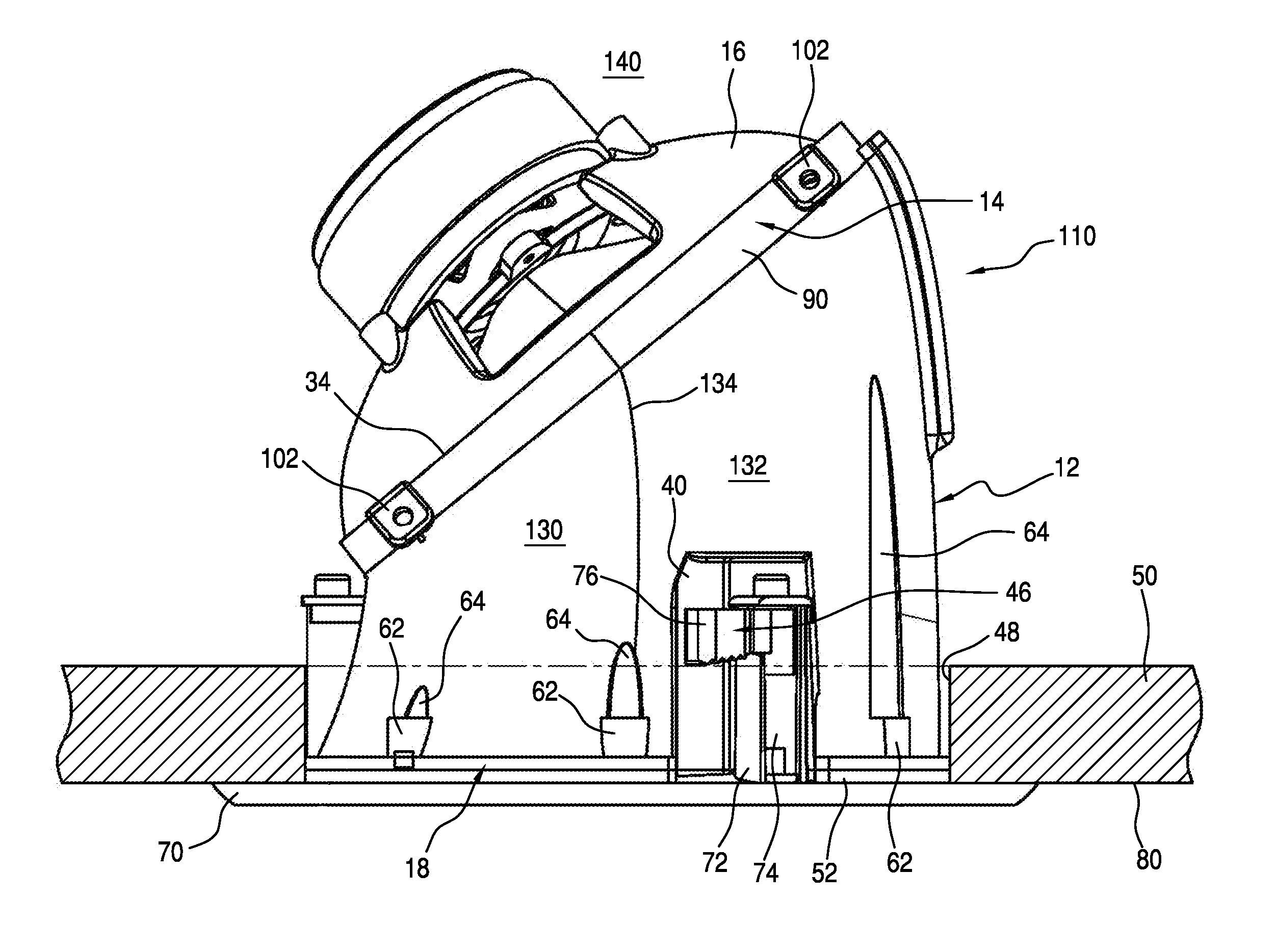
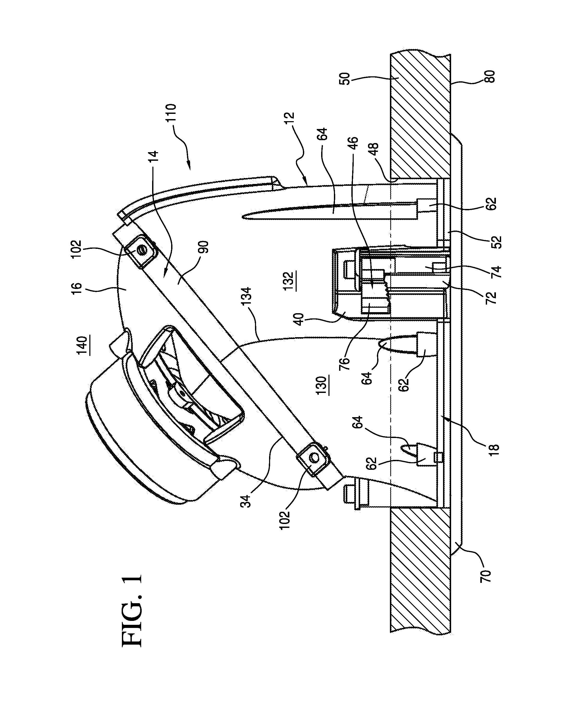
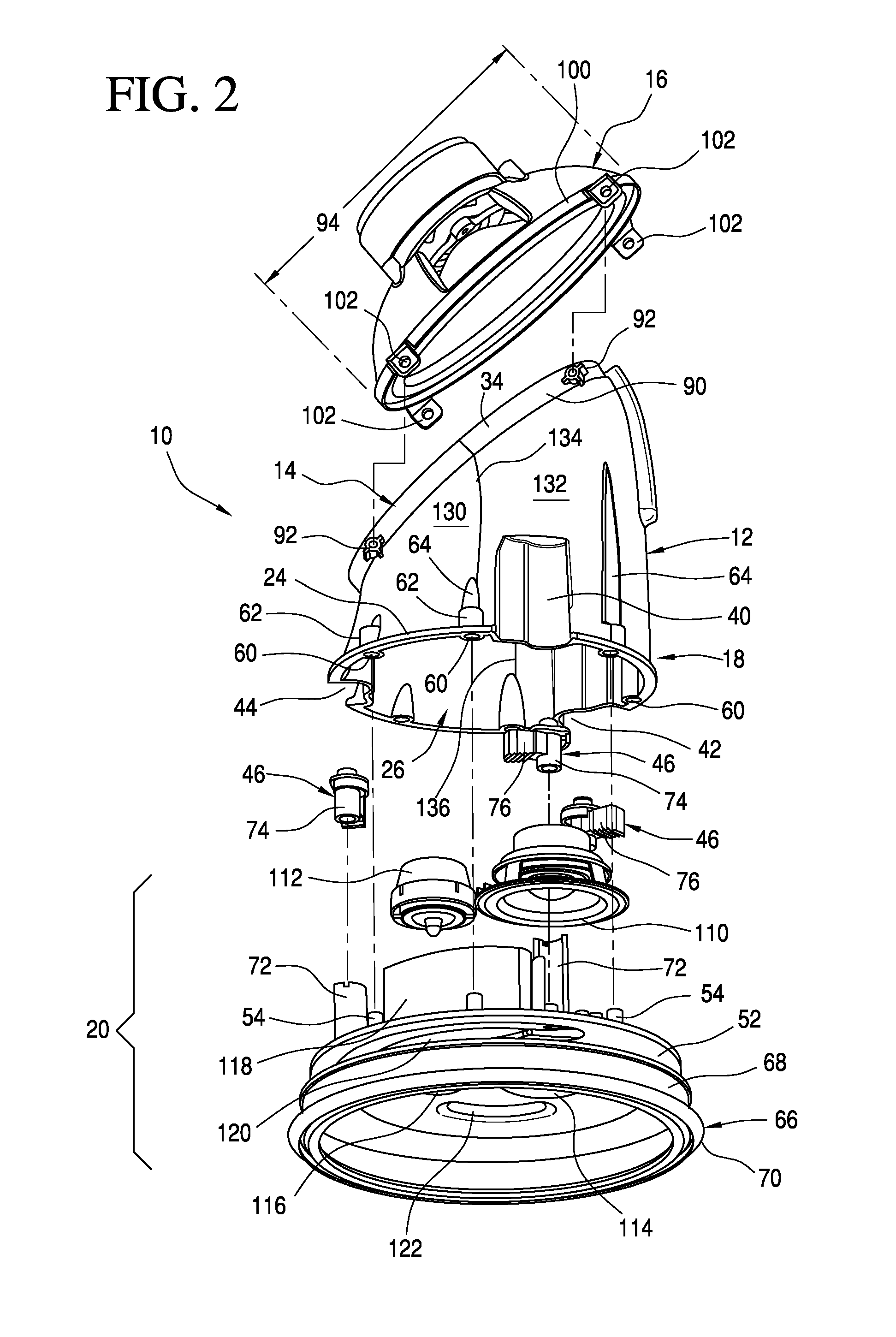
[0021]Referring now to the embodiment of the invention illustrated in FIGS. 1 to 4, a ceiling loudspeaker assembly generally indicated at 10 comprises a horn-shaped enclosure 12 supporting at its upper end 14 an acoustic driver 16 and at its bottom end 18 a speaker module 20. Hollow, generally tubular enclosure 12 serves as a horn-shaped acoustic waveguide for the low-range speaker or acoustic driver 16, which may be a woofer driver, for example, and may be suitably driven to generate an acoustic sound which travels through the hollow enclosure's interior lumen or waveguide and through the speaker module 20, which then facilitates sound dispersion outwardly, or when mounted in a ceiling, downwardly, as viewed in the Figures.

[0022]As illustrated, the horn enclosure 12 is generally tubular; that is, it has a substantially circular cross-section in a plane, such as the lower or proximal plane 22 defined by the circumference of the rim 24 of the bottom opening 26 (FIG. 2) at the bottom ...


PUM


Abstract

A ceiling-mounted loudspeaker includes a horn-shaped enclosure, an acoustic driver, and a front module. The tubular or horn-shaped enclosure carries a slanted woofer or loudspeaker driver which radiates into an angled or slanted first opening. The tubular enclosure terminates at bottom in a second, circular opening substantially parallel to a second plane, wherein the woofer's slanted plane is inclined with respect to the second plane. The slanted woofer can be oval and radiates sound through the enclosure's interior lumen and outwardly through ports defined in a substantially circular baffle carrying the front module and connected to the second opening. The baffle carries a midrange and tweeter near the ceiling where they can provide enhanced sound dispersion.

Description

RELATED APPLICATION INFORMATION AND PRIORITY CLAIM[0001]This application claims priority to and the benefit of co-pending U.S. Provisional Patent Application No. 61 / 220,917, filed 26 Jun. 2009, and entitled “Ceiling Loudspeaker and Enclosure” the entire disclosure of which is incorporated herein by reference.TECHNICAL FIELD[0002]The present invention relates, in general, to a ceiling loudspeaker and in particular to a ceiling loudspeaker with a horn-shaped enclosure.BACKGROUND OF THE INVENTION[0003]Ceiling-mounted audio loudspeakers are well known in the art and have been commercially available for many years. Examples of such loudspeakers can be found in U.S. Pat. No. 5,088,574; U.S. Pat. No. 6,870,943; and U.S. Pat. No. 7,142,680, among other places. A ceiling loudspeaker is usually mounted in a hole that is cut in a ceiling structure, such as a ceiling tile, with the speaker being inserted through the hole and mounted to the tile or other plenum structure. The trend in interior d...

Claims


Application Information

Patent Timeline
Patent Type & Authority Applications(United States)
IPC IPC(8): H04R1/02
CPCH04R1/26H04R2201/021H04R1/2842
Inventor SMITH, L.J.LUMSDEN, STUART W.ORTH, SCOTT
Owner POLK AUDIO LLC
Why Eureka
Try Eureka