Simulation of the image projected by a mask

Active Publication Date: 2011-01-27
STMICROELECTRONICS CROLLES 2
View PDF4 Cites 11 Cited by
  • Summary
  • Abstract
  • Description
  • Claims
  • Application Information

AI Technical Summary

Benefits of technology

[0013]It is an aim of embodiments of the present invention to at le

Problems solved by technology

This distortion results from some dispersion and interference on the light as it passes through the mask and through the optical arrangement between the mask and the wafer.
Therefore, the 3D mask effects that are ignored by the Kirchhoff or thin mask model are no longer negligible.
A problem with the DDM

Method used


Image

  • Simulation of the image projected by a mask
  • Simulation of the image projected by a mask
  • Simulation of the image projected by a mask

Examples


Embodiment Construction

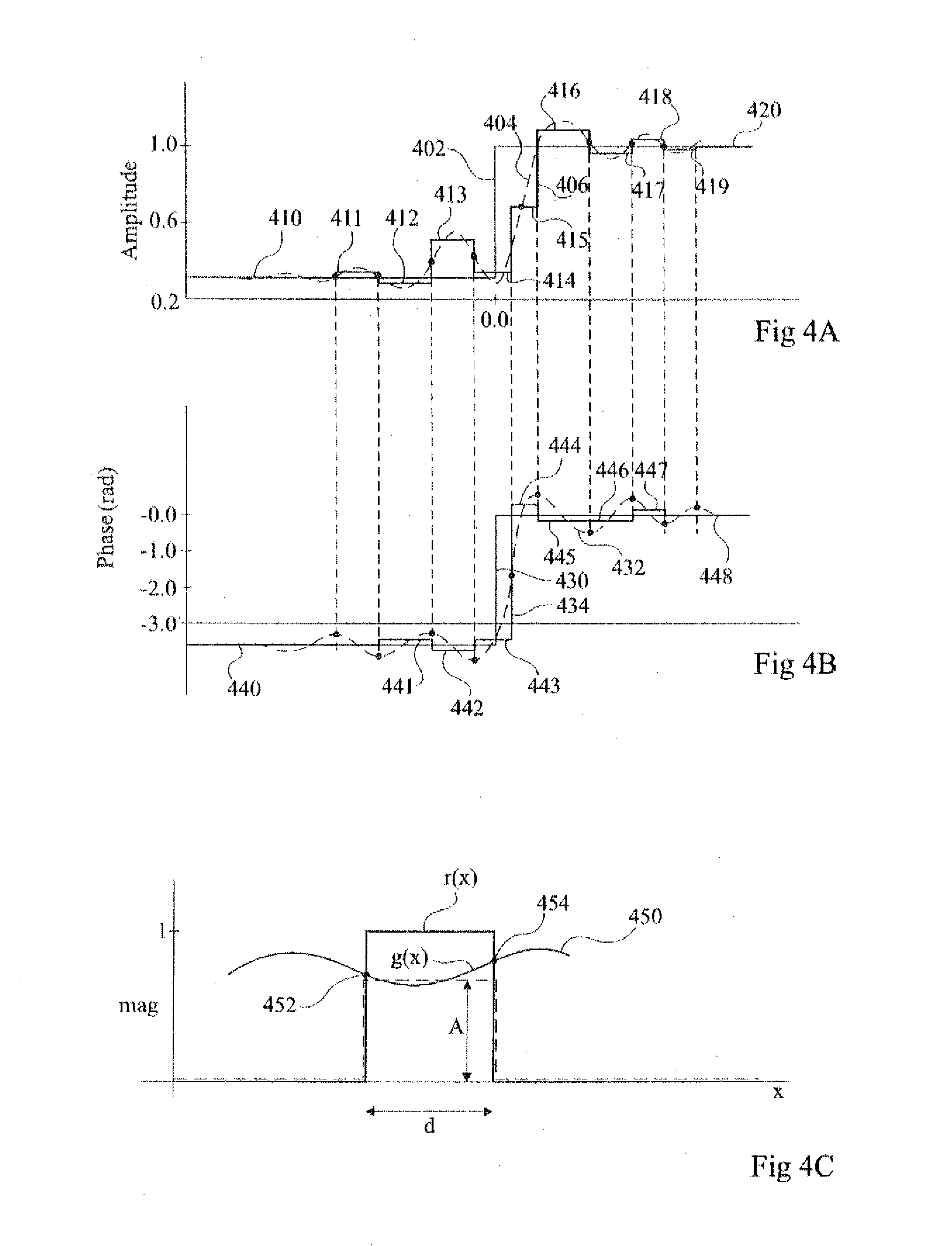
[0038]FIGS. 4A and 4B show curves of estimations of near-field transmission amplitude and phase respectively resulting from a pattern boundary of the mask at position 0.0 in the middle of the x axis in each figure.

[0039]In FIG. 4A, the curve 402 illustrates a near-field transmission approximation based on the Kirchhoff model, according to which the near-field transmission amplitude corresponds to a step function at the pattern boundary. To the left of the step, the opaque part of the mask is present, and the near-field transmission amplitude is assumed to be at a constant low value, for example around 6%. To the right of the step, the transparent region of the mask is present, and the near-field transmission amplitude is assumed to be at a high value of around 100%.

[0040]The dashed curve 404 illustrates the near-field around the pattern boundary based on a rigorous EMF simulation, based on the actual thickness of the opaque layer of the mask. As illustrated, due to the thickness of ...


PUM


Abstract

The disclosure concerns a method of simulating the image projected by a mask during photolithography including determining by a processor (702), taking into account the thickness of a masking layer of a mask, a near-field transmission amplitude curve of light passing through the mask across at least one pattern boundary in the initial mask layout; calculating by the processor, for each of a plurality of zones, average values of the curve; and simulating by a simulator (708) the image projected by the initial mask layout during the photolithography based on the average values.

Description

FIELD OF THE INVENTION[0001]The present invention relates to methods and apparatus for simulating the image projected by a mask during photolithography, generating a final mask layout, fabricating a mask based on the final mask layout and fabricating an integrated circuit using the mask.BACKGROUND OF THE INVENTION[0002]FIG. 1 illustrates a photolithography step involving a semiconductor wafer 2, having a light sensitive photo-resist 4 formed on it A mask 6 is positioned over the semiconductor wafer 2 and comprises a transparent plate 7 and opaque regions 8 on the underside of the plate 7 forming an image that is projected onto the photo-resist 4 during a photolithography step. The plate 7 is for example made of quartz, and the opaque regions B are formed for example of molybdenum suicide (MoSi). As represented in FIG. 1, light 10 is shone through the mask 6, and an image reducing lens 12 is used to make a reduction in the size of the image projected on the photo-resist 4, such that ...

Claims


Application Information

Patent Timeline
IPC IPC(8): G06F19/00G06F17/10
CPCG03F1/36G03F1/144
Inventor SAIED, MAZENYESILADA, EMEK
Owner STMICROELECTRONICS CROLLES 2
Why Eureka
Try Eureka