Exhaust gas treatment device

a gas treatment device and exhaust gas technology, applied in the direction of exhaust treatment, combination devices, mechanical devices, etc., can solve the problems of clogging the particle filter, reducing the efficiency of the exhaust gas treatment device,

Active Publication Date: 2011-02-03
EBERSPACHER EXHAUST TECH GMBH & CO KG
View PDF8 Cites 33 Cited by
  • Summary
  • Abstract
  • Description
  • Claims
  • Application Information

AI Technical Summary

Benefits of technology

The object of the present invention is to propose an improved embodiment for an exhaust gas treatment device of the type mentioned in the introduction, which is characterized in that the accessibility to the respective unit for maintenance purposes and the like is simplified.
The present invention is based on the general idea of axially rigidly arranging a bracket at the particle filter unit and of axially fixing said bracket to the housing by means of a clamp connection, which detachably connects at least two housing parts adjoining each other axially with one another. The clamp connection, which is present anyway, assumes an additional function hereby, because it fixes the two adjacent housing parts to one another, on the one hand, and because it fixes the bracket to the housing, on the other hand. By releasing the clamp connection, the housing parts are mobile in relation to one another, on the one hand, whereas the bracket is also mobile relative to the housing, on the other hand. In particular, the particle filter unit can then be removed from the housing in an especially simple manner.

Problems solved by technology

Furthermore, residues that cannot be burned off may remain in the particle filter unit, and these residues increasingly collect over time and gradually clog the particle filter in question.
A comparatively great effort is needed to remove the oxidation-type catalytic converter unit and / or the particle filter unit from the common housing.

Method used


Image

  • Exhaust gas treatment device
  • Exhaust gas treatment device
  • Exhaust gas treatment device

Examples


Embodiment Construction

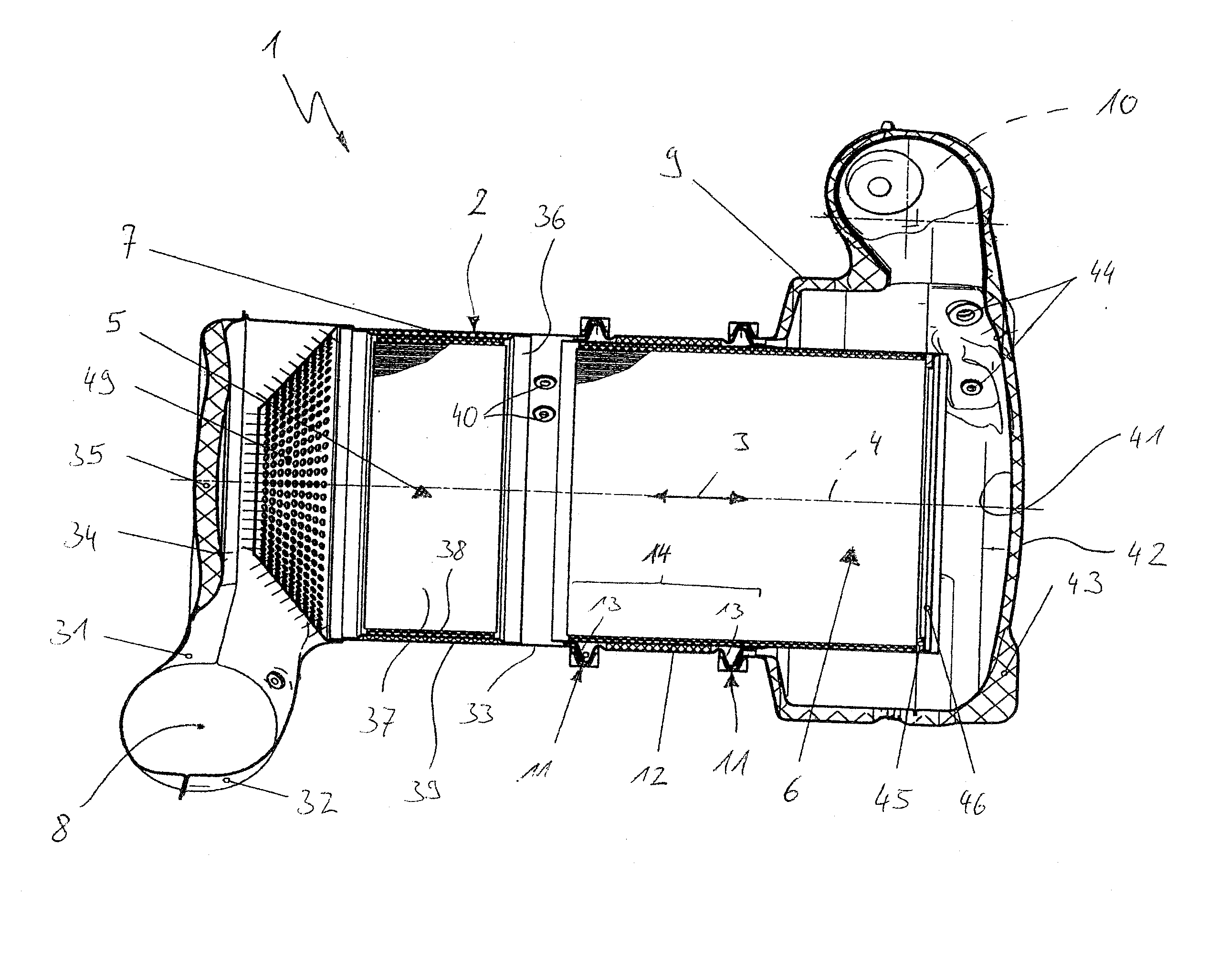
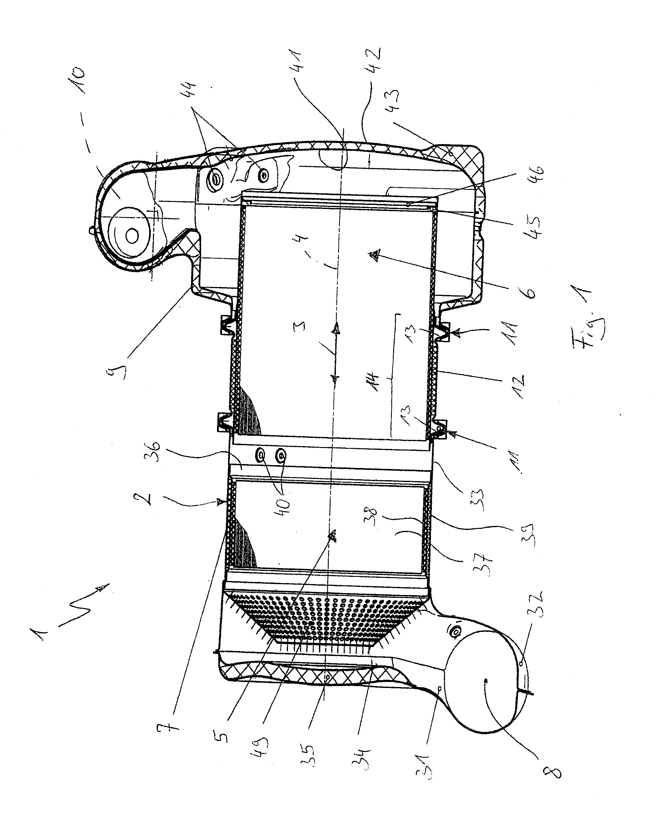
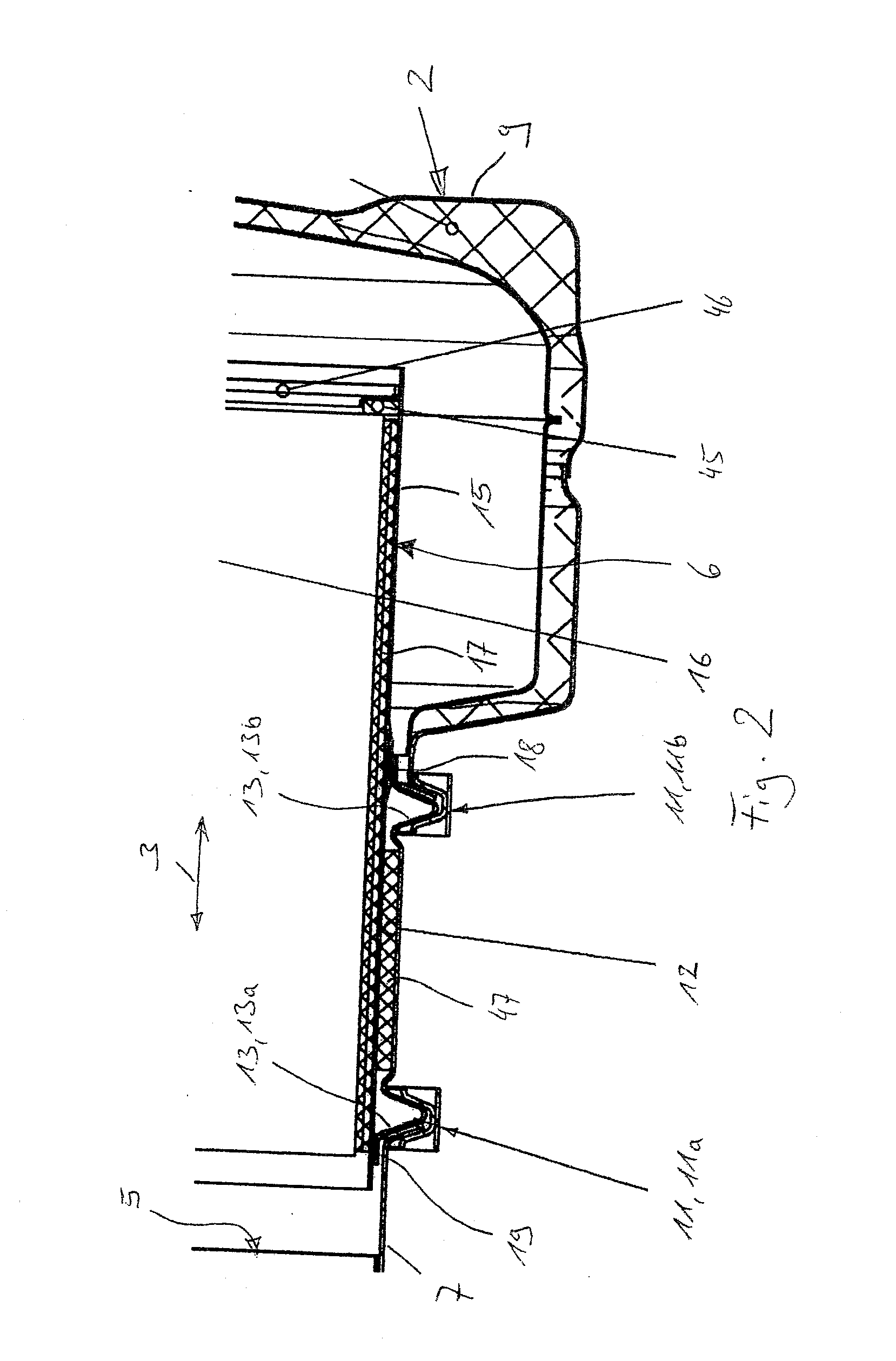
Referring to the drawings in particular, corresponding to FIG. 1, an exhaust gas treatment device 1 is provided, which can be used in an exhaust system of an internal combustion engine. The internal combustion engine is preferably located in a motor vehicle. The exhaust gas treatment device 1 comprises a multipart housing 2, which extends in a longitudinal direction 3. The longitudinal direction 3 of the housing extends here parallel to a central longitudinal axis 4 of housing 2 and defines an axial direction, which will hereinafter be likewise designated by 3. In respect to this axial direction 3, housing 2 contains an oxidation-type catalytic converter unit 5 and a particle filter unit 6 arranged downstream thereof one behind the other.

Housing 2 has an inlet housing part 7, which is equipped with an exhaust gas inlet 8 and in which the oxidation-type catalytic converter 5 is arranged. Furthermore, housing 2 has an outlet housing part 9, which has an exhaust gas outlet 10 and into ...


PUM

PropertyMeasurementUnit
axial lengthaaaaaaaaaa
ignition temperatureaaaaaaaaaa
areaaaaaaaaaaa

Abstract

An exhaust gas treatment device (1) for an exhaust system of an internal combustion engine, especially of a motor vehicle, has a multipart housing (2), which contains an oxidation-type catalytic converter unit (5) and, downstream therefrom, a particle filter unit (6) one after another in an axial direction extending in parallel to a longitudinal direction (3) of the housing. The housing (2) contains an inlet housing part (7), which has an exhaust gas inlet (8) and the oxidation-type catalytic converter unit (5), and an outlet housing part (9), which has an exhaust gas outlet (10) and into which the particle filter unit (6) axially protrudes. The maintenance of the exhaust gas treatment device is simplified if at least two housing parts (7, 9, 12) axially adjoining each other are detachably connected to one another by means of a clamp connection (11) and if at least one bracket (13) is provided, which is axially rigid in relation to the particle filter unit (6) and which cooperates with at least one such clamp connection (11), such that the bracket (13) is axially fixed at least one housing part (7, 9, 12) by means of the respective clamp connection (11).

Description

CROSS REFERENCE TO RELATED APPLICATIONSThis application claims the benefit of priority under 35 U.S.C. §119 of German patent application DE 10 2009 024 534.0 filed Jun. 10, 2009 the entire contents of which are incorporated herein by reference.FIELD OF THE INVENTIONThe present invention pertains to an exhaust gas treatment device for an exhaust system of an internal combustion engine, especially of a motor vehicle.BACKGROUND OF THE INVENTIONExhaust gas treatment device are, for example, catalytic converters and particle filters as well as combinations thereof. For example, an oxidation-type catalytic converter unit as well as a particle filter unit may be arranged one after another in a common housing to achieve a compact design. Hydrocarbons being carried in the exhaust gas can be reacted by means of the oxidation-type catalytic converter. The particle filter removes particles being carried in the exhaust gas, especially soot. Fuel, which is reacted at the catalytic converter exoth...

Claims


Application Information

Patent Timeline
Patent Type & Authority Applications(United States)
IPC IPC(8): F01N3/035
CPCF01N3/035F01N13/1811F01N13/0097F01N2470/00F01N2240/20
Inventor WERNI, MARCUSBAY, MICHAELDATZ, WOLFGANG
Owner EBERSPACHER EXHAUST TECH GMBH & CO KG
Why Eureka
Try Eureka