
Micromechanical acceleration sensor

a technology of acceleration sensor and micro-mechanical body, which is applied in the direction of acceleration measurement in multiple dimensions, acceleration measurement using interia force, instruments, etc., can solve the problem of not being well suited to detecting accelerations which are relatively large in absolute value, and achieve cost-effective effects

Active Publication Date: 2011-02-03
CONTINENTAL TEVES AG & CO OHG
View PDF26 Cites 45 Cited by
  • Summary
  • Abstract
  • Description
  • Claims
  • Application Information

AI Technical Summary

Benefits of technology

[0004]An object of the present invention is to propose a micromechanical acceleration sensor which can detect relatively precisely at least two different accelerations which differ significantly at least in absolute value, and at the same time is in particular relatively cost-effective.
[0008]The acceleration sensor according to aspects of the invention additionally has the advantage that, by means of the at least one frame, essentially decoupled detection of accelerations in different directions can be additionally carried out relatively precisely and easily.
[0017]It is preferred that the base surface of the substrate is oriented parallel to the x-y plane of a Cartesian coordinate system, and the first frame is suspended on the substrate such that it can be deflected in the x direction or y direction, wherein the first seismic mass is suspended on the first frame or an additional frame such that it can be deflected at least in the z direction, and the acceleration sensor has at least two electrodes which are substantially in particular plate-shaped, are arranged essentially parallel to the x-y plane and are assigned to the first seismic mass as a reading device. The electrodes are particularly preferably arranged in the z direction below and / or above the first seismic mass. In each case one of the electrodes is very particularly preferably arranged on one side of the torsion axis with respect to the x-y plane, and the other electrode is arranged on the other side. As a result, opposing changes in capacitance can be detected, as a result of which the absolute capacitance, which possibly changes over time, does not have to be taken into account. It is therefore possible to carry out differential signal processing.
[0018]It is expedient that at least one of the electrodes is arranged in the z direction above the seismic mass, and at least one other of the electrodes is arranged in the z direction below the seismic mass. This design permits both differential detection of the deflection of the seismic mass and the construction of the acceleration sensor or of electrodes of the acceleration sensor on a relatively small area, in particular with respect to the x-y plane.
[0023]It is preferred that at least the first seismic mass has, at least on its surface lying opposite the electrodes, trenches which are each formed in particular essentially parallel to one another. A defined geometric design of these trenches allows defined damping of the deflection of the seismic mass to be set, particularly preferably by means of the number and width of these trenches.
[0024]At least one spring element on which a seismic mass or a frame is suspended, and / or at least one torsion spring on which a seismic mass or a frame is suspended, expediently has / have at least one piezo-sensitive element. The at least one piezosensitive element is in particular a piezoresistive element or a piezoelectric element. A piezoresistive element particularly preferably comprises in this context at least one resistance bridge which is particularly preferably applied to one or more spring elements or torsion springs. By means of a piezosensitive element it is possible to detect the deflection of a seismic mass or of a frame without an additional reading device, in the form of a comb structure or an electrode, or such a piezosensitive element can replace a reading device in the form of a capacitive structure, as a result of which the area or chip area of the acceleration sensor can be kept relatively small, in particular with respect to the x-y plane.

Problems solved by technology

This acceleration sensor is relatively well suited to detecting accelerations which are relatively small in absolute value, but it is less well suited to detecting accelerations which are relatively large in absolute value.

Method used


Image

  • Micromechanical acceleration sensor
  • Micromechanical acceleration sensor
  • Micromechanical acceleration sensor

Examples


Embodiment Construction

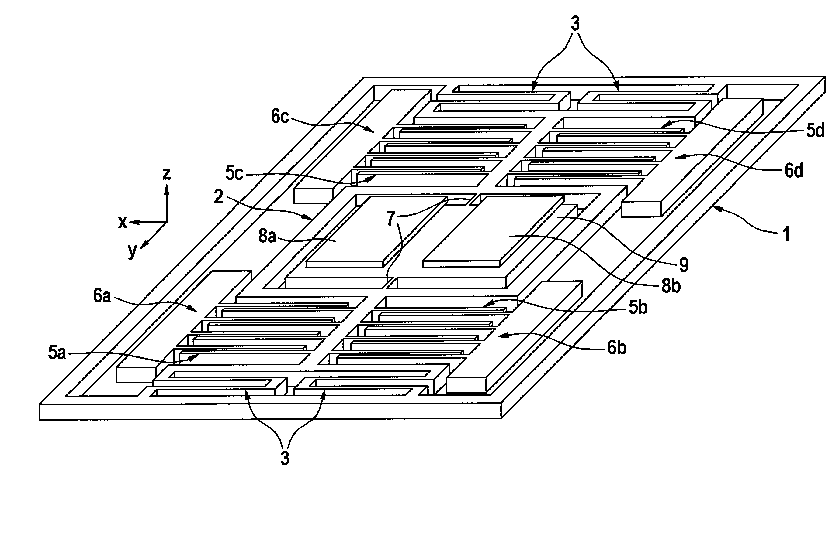
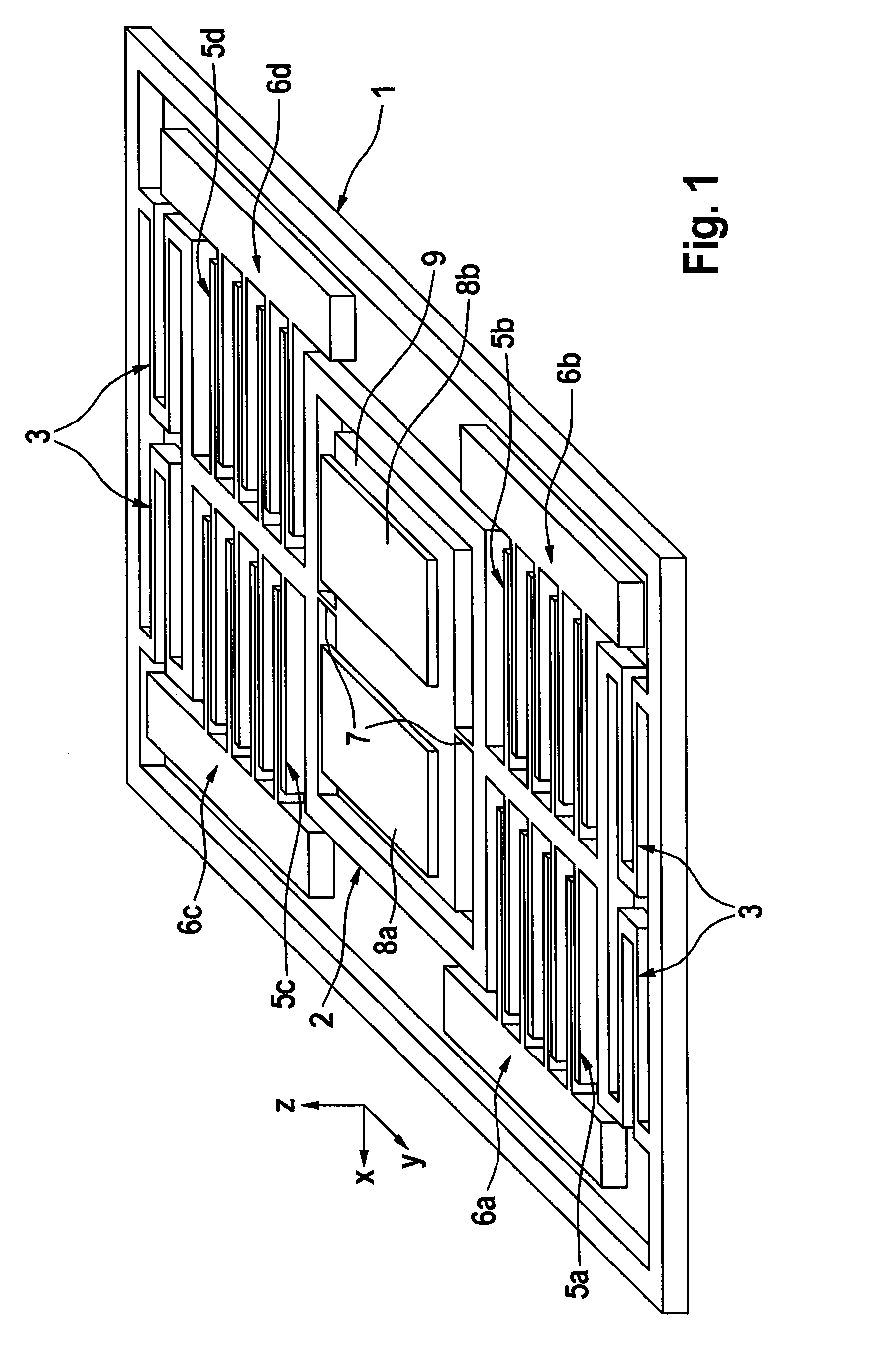
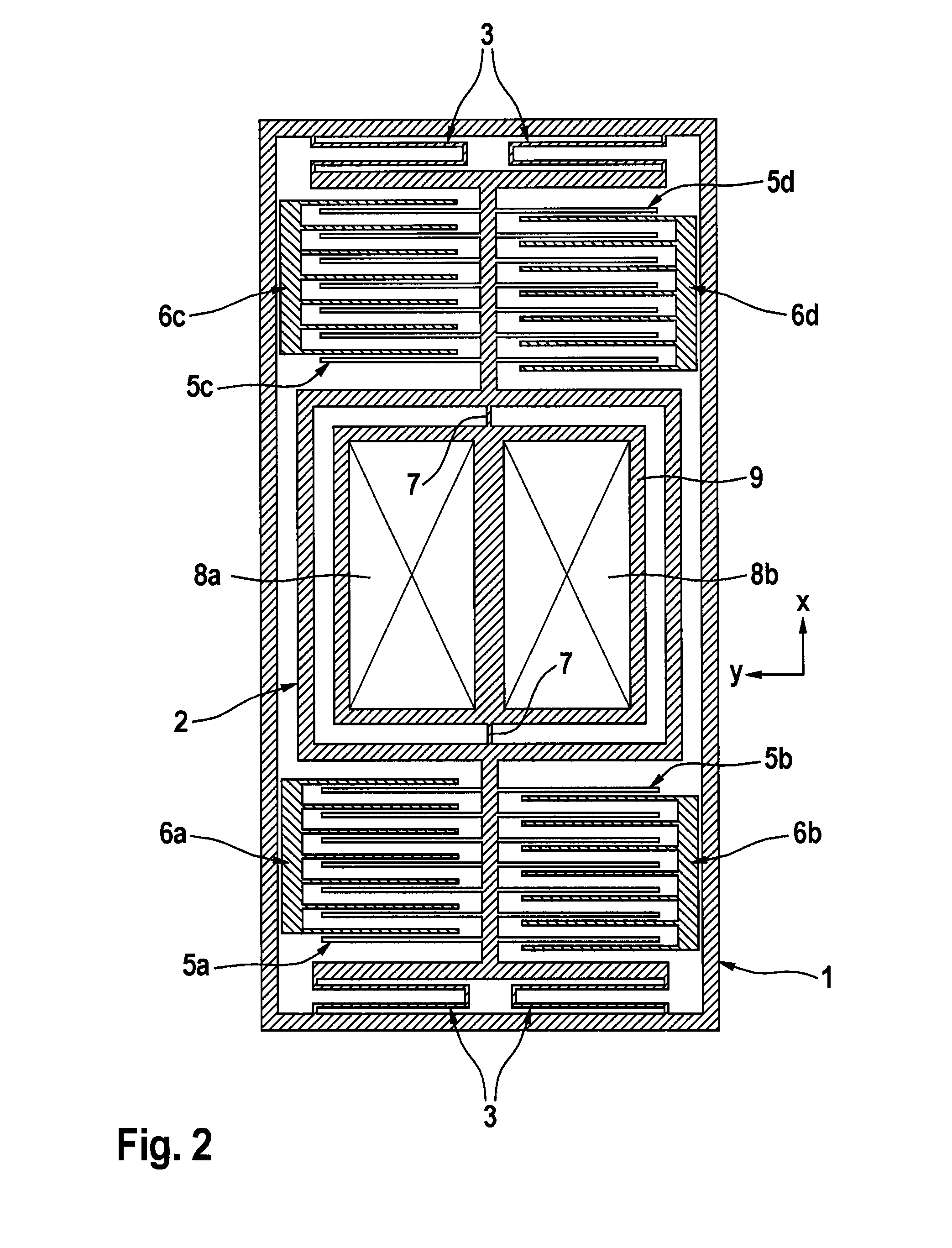
[0047]An exemplary embodiment of an acceleration sensor is illustrated in a spatial illustration in FIG. 1, and in plan view in FIG. 2. This acceleration sensor comprises a substrate which is embodied as a frame 1. The substrate frame 1 is oriented here, as depicted, with respect to the Cartesian x-y-z coordinate system. Furthermore, the substrate or frame 1 is firmly and rigidly directly or indirectly connected to, for example, the inertial system on which the accelerations which are to be detected primarily act. In the substrate frame 1a first deflectable frame 2 is suspended thereon by means of spring elements 3. The spring elements 3 permit a movement of the frame 2 or of the first deflectable frame in the direction of a measuring direction parallel to the y axis, but they are rigidly embodied in the spatial directions x and z. The measuring direction parallel to the y axis corresponds to the direction for the detection of relatively large accelerations (high-G). Parallel the x ...


PUM

PropertyMeasurementUnit
Massaaaaaaaaaa
Gravityaaaaaaaaaa
Sensitivityaaaaaaaaaa

Abstract

A micromechanical acceleration sensor, including at least one substrate, one or more frames, at least a first frame of which is suspended directly or indirectly on the substrate by at least one spring element, and is deflected with respect to the substrate when at least a first acceleration acts, and at least a first seismic mass which is suspended on the first frame or an additional frame by at least one spring element, and is deflected with respect to this frame when an acceleration acts which is, in particular, different from the first acceleration.

Description

CROSS REFERENCE TO RELATED APPLICATIONS[0001]This application is the U.S. national phase application of PCT International Application No. PCT / EP2009 / 054052, filed Apr. 3, 2009, which claims priority to German Patent Application No. 10 2008 017 156.5, filed Apr. 3, 2008, the content of such applications being incorporated by reference herein.FIELD OF THE INVENTION[0002]The invention relates to a micromechanical acceleration sensor, to a method for manufacturing an acceleration sensor, and to the use of the acceleration sensor in motor vehicles.BACKGROUND OF THE INVENTION[0003]Document WO 03 / 104823, which is incorporated by reference, proposes a micromechanical capacitive acceleration sensor for detecting accelerations in a plurality of spatial directions, which comprises a plurality of seismic masses with torsion suspensions which are oriented differently with respect to one another, wherein the seismic masses are each suspended eccentrically with respect to their center of gravity. ...

Claims


Application Information

Patent Timeline
IPC IPC(8): G01P15/125H05K3/00G01P15/18
CPCY10T29/49124G01P15/18G01P15/125
Inventor BURGHARDT, ROLANDHILSER, ROLANDSCHMID, BERNHARDALBRECHT, VEITHTHEOBALD, DIRK
Owner CONTINENTAL TEVES AG & CO OHG
Learn More