Engine brake unit

a technology for engine brakes and units, applied in valve arrangements, machines/engines, pressure lubrication, etc., can solve the problems of increasing reducing the life of the engine, and reducing the amount of load applied to the respective parts of the engine, so as to reduce the space where hydraulic pressure is applied, reduce the number of parts, and reduce the weight and manufacturing costs

Active Publication Date: 2011-02-03
HYUNDAI MOTOR CO LTD +1
View PDF43 Cites 15 Cited by
  • Summary
  • Abstract
  • Description
  • Claims
  • Application Information

AI Technical Summary

Benefits of technology

[0021]According to various aspects of the present invention, the engine brake unit can reduce weight and manufacturing costs by reducing the number of parts. In addit...

Problems solved by technology

In engine braking, however, an excessive amount of load is applied to respective parts of an engine since the transmission is down-shifted.
This may cause drawbacks such as reduced engine life.
However, the engine brake unit located in a separate...

Method used


Image

  • Engine brake unit
  • Engine brake unit
  • Engine brake unit

Examples


Embodiment Construction

[0030]Reference will now be made in detail to various embodiments of the present invention(s), examples of which are illustrated in the accompanying drawings and described below. While the invention(s) will be described in conjunction with exemplary embodiments, it will be understood that present description is not intended to limit the invention(s) to those exemplary embodiments. On the contrary, the invention(s) is / are intended to cover not only the exemplary embodiments, but also various alternatives, modifications, equivalents and other embodiments, which may be included within the spirit and scope of the invention as defined by the appended claims.

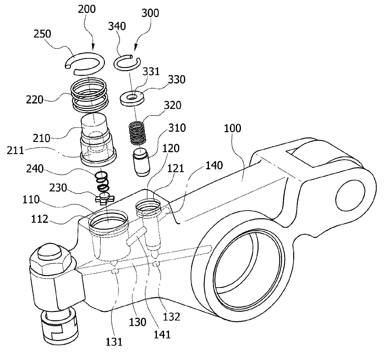
[0031]FIG. 2 is an exploded perspective view illustrating an engine brake unit in accordance with an exemplary embodiment of the invention, and FIG. 3 is a cross-sectional view illustrating the engine brake unit shown in FIG. 2.

[0032]The engine brake module of this embodiment includes a rocker arm 100, a stopper 410, an actuator 200, ...


PUM


Abstract

An engine brake unit may include a rocker arm having a first space defined in a valve-pressing portion thereof, wherein the first space communicates with a supply passage, through which engine brake oil is introduced, a stopper fixedly provided above the first space of the rocker arm in a predetermined distance, an actuator located inside the first space and having a pressure piston, wherein the pressure piston is selectively raised by hydraulic pressure of the engine brake oil to butt against the stopper, thereby pressing a portion of the rocker arm downwards.

Description

CROSS REFERENCE TO RELATED APPLICATION[0001]The present application claims priority to Korean Patent Application Number 10-2008-0070724 filed on Jul. 31, 2009, the entire contents of which application is incorporated herein for all purposes by this reference.BACKGROUND OF THE INVENTION[0002]1. Field of the Invention[0003]The present invention relates to an engine brake unit, in particular, to one which is located inside an inner space of a rocker arm to reduce size and weight, so as to increase the flow rate of engine brake oil due to a reduction in the volume of a closed circuit where pressure is created, thereby improving the performance thereof.[0004]2. Description of Related Art[0005]Engine braking generally refers to the act of slowing down a vehicle by down-shifting to a lower transmission gear. In engine braking, however, an excessive amount of load is applied to respective parts of an engine since the transmission is down-shifted. This may cause drawbacks such as reduced eng...

Claims


Application Information

Patent Timeline
IPC IPC(8): F02D13/04
CPCF01L13/06F01L1/181F01L1/18F01M1/06F02D13/04
Inventor YOON, SEOCK JOONGKIM, KYUNG MO
Owner HYUNDAI MOTOR CO LTD
Why Eureka
Try Eureka