Method to Control Driving Fluid Breakthrough During Production of Hydrocarbons from a Subterranean Reservoir

a technology of hydrocarbons and hydrocarbons, which is applied in the direction of sealing/packing, well accessories, ceramics, etc., can solve the problems of increasing water oil ratio, reducing oil production, and increasing the difficulty of reducing so as to reduce the flow rate of water communication

Inactive Publication Date: 2011-02-03
BP CORP NORTH AMERICA INC
View PDF45 Cites 17 Cited by
  • Summary
  • Abstract
  • Description
  • Claims
  • Application Information

AI Technical Summary

Benefits of technology

[0025]allowing the polymer gel precursor to set for a time sufficient to thereby form a plug comprised of the polymer

Problems solved by technology

When this pressure communication develops, the producer well exhibits a breakthrough of injected water and thus an increase in the water oil ratio and decrease in oil production.
This breakthrough of injection water is a serious disadvantage and becomes more prevalent as the oil field matures.
Conventional waterflooding of heavy/viscous oil reservoirs is plagued with either very large pressure gradients or premature water breakthrough as previously mentioned, and both these aspects can lead to low injectivity or poor sweep efficiency, thereby resulting in poor oil recovery.
Further, because of the increased viscosity of the heavy oil, it is susceptible to fingering.
In addition, the matrix of the rock becomes weaker and weaker as the process continues, even to the point where it is believed that a portion of the rock formation can fail and produce large volumes of sand and leave a “void” in the reservoir.
The water fingering makes the waterflood process very ineffic

Method used


Image

  • Method to Control Driving Fluid Breakthrough During Production of Hydrocarbons from a Subterranean Reservoir
  • Method to Control Driving Fluid Breakthrough During Production of Hydrocarbons from a Subterranean Reservoir
  • Method to Control Driving Fluid Breakthrough During Production of Hydrocarbons from a Subterranean Reservoir

Examples


example

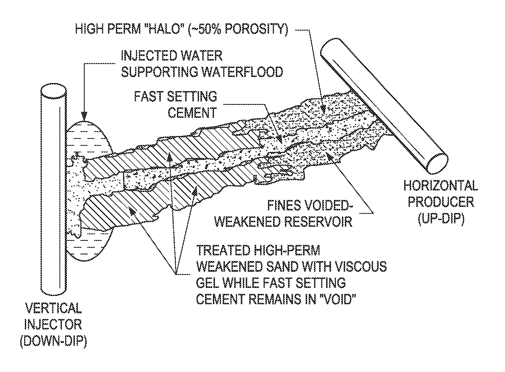
Remediation of High Permeability Zone Using Combined Cement and Gel Treatments

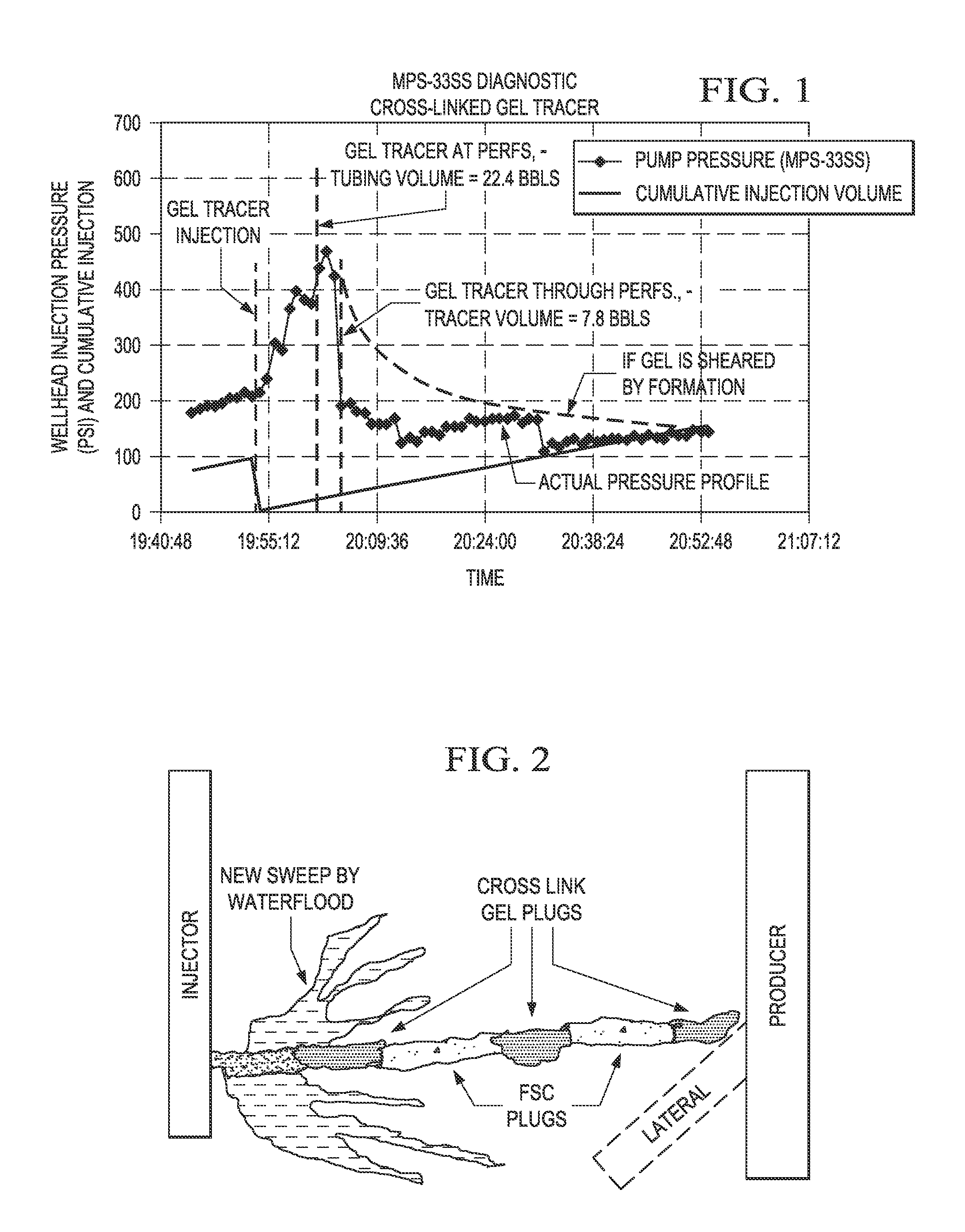
[0084]The procedure of the Comparative Example is substantially repeated to place the cement plugs into the void space of the high permeability zones within the two injector and producer well pairs. After treatment, the cement plugs are placed into the zone substantially as depicted in FIG. 2. It is believed that this step essentially plugs pressure communication between the injection wells and production wells through the void space of the zone.

[0085]While placement of the cement plugs results in some success, pressure communication between the injector and producer pairs appears again after a relatively short period of 39 and 50 days respectively for the two well pairs, as previously indicated in the Comparative Example. A red dye tracer test is again run on the injector and producer well pairs, together with pressure interference testing, which confirms the presence of what is believed to be an associat...


PUM

PropertyMeasurementUnit
Percent by massaaaaaaaaaa
Viscosityaaaaaaaaaa

Abstract

The invention is directed to a method for controlling driving fluid breakthrough caused by zones of pressure communication, i.e., a matrix bypass event (“MBE”) or a wormhole, having a void space and possibly areas of enhanced permeability (a halo region) associated with the void space, within a subterranean formation arising from use of a driving fluid in reservoirs where heavy/viscous oil is being produced. In particular, the method is directed to remediation of pressure communication between injection and production wells used to produce heavy/viscous oil by way of a waterflood operation combined with a cold production method. Direct or rapid communication of water between the injector and producer wells makes the waterflood recovery process virtually ineffective and limits the production of oil from the reservoir. The invention comprises in embodiments a method wherein a slurry of a cementitious material is injected into the zone, which upon setting, provides a cement plug in the void space that reduces the pressure communication and flow of driving fluid within the zone. Another step is used to inject a gel precursor within the zone, which upon setting, produces a gel plug that also reduces pressure communication and driving fluid flow through the halo region of the zone.

Description

CROSS-REFERENCE TO RELATED APPLICATIONS[0001]This application claims benefit of U.S. Provisional Patent Application Ser. No. 61 / 230,443, filed Jul. 31, 2009, the teachings of which are incorporated herein by reference in their entirety.FIELD OF THE INVENTION[0002]The present invention relates to a method for remediation and / or inhibition of driving fluid breakthrough during production of hydrocarbons, and in particular heavy / viscous oil, from a subterranean reservoir, such as where a pressure communication between an injection well and a production well arises during a waterflood operation.BACKGROUND OF THE INVENTION[0003]Many oil fields are comprised of reservoirs wherein the injection wells involved with a waterflood operation have or develop direct or indirect pressure communication with offset production wells. When this pressure communication develops, the producer well exhibits a breakthrough of injected water and thus an increase in the water oil ratio and decrease in oil pro...

Claims


Application Information

Patent Timeline
IPC IPC(8): E21B33/13
CPCC04B28/04C04B28/30C04B28/32C09K8/44C09K8/46E21B43/32C09K8/508C09K8/512C09K8/5045C04B38/10
Inventor BRICE, BRADLEY W.BOCCARDO, GIOVANNATREMBLAY, BERNARD
Owner BP CORP NORTH AMERICA INC
Why Eureka
Try Eureka