Lubricating device and method for gearbox

a lubricating device and gearbox technology, applied in the direction of gearing details, mechanical equipment, machines/engines, etc., can solve the problems of reducing the and affecting the service life of the pump

Inactive Publication Date: 2011-02-03
MITSUBISHI HEAVY IND LTD
View PDF7 Cites 19 Cited by
  • Summary
  • Abstract
  • Description
  • Claims
  • Application Information

AI Technical Summary

Benefits of technology

[0038]According to the present invention as described above, the lubricating device and lubricating method for a gearbox which does not take long to heat t

Problems solved by technology

If the splashing of the lubricant continues, the lubricant oil in the oil pan becomes clouded and a lot of air gets in the lubricant oil.
When the lubricant oil with high air content is circulated, aeration occurs and abnormal noises and vibration are generated from the pump, resulting in dec

Method used


Image

  • Lubricating device and method for gearbox
  • Lubricating device and method for gearbox
  • Lubricating device and method for gearbox

Examples


first embodiment

[0044]FIG. 3 illustrates a whole structure of a wind turbine of a first embodiment and FIG. 4 is a schematic structure of a nacelle of the first embodiment. A horizontal axis wind turbine is used in the present embodiment but should not limit a type of a wind turbine thereto.

[0045]As shown in FIG. 3, a horizontal axis wind turbine 50 of the present embodiment comprises a tower 58, a nacelle 52, a hub 54 and blades 56. The blades 56 are fixed to the hub 54.

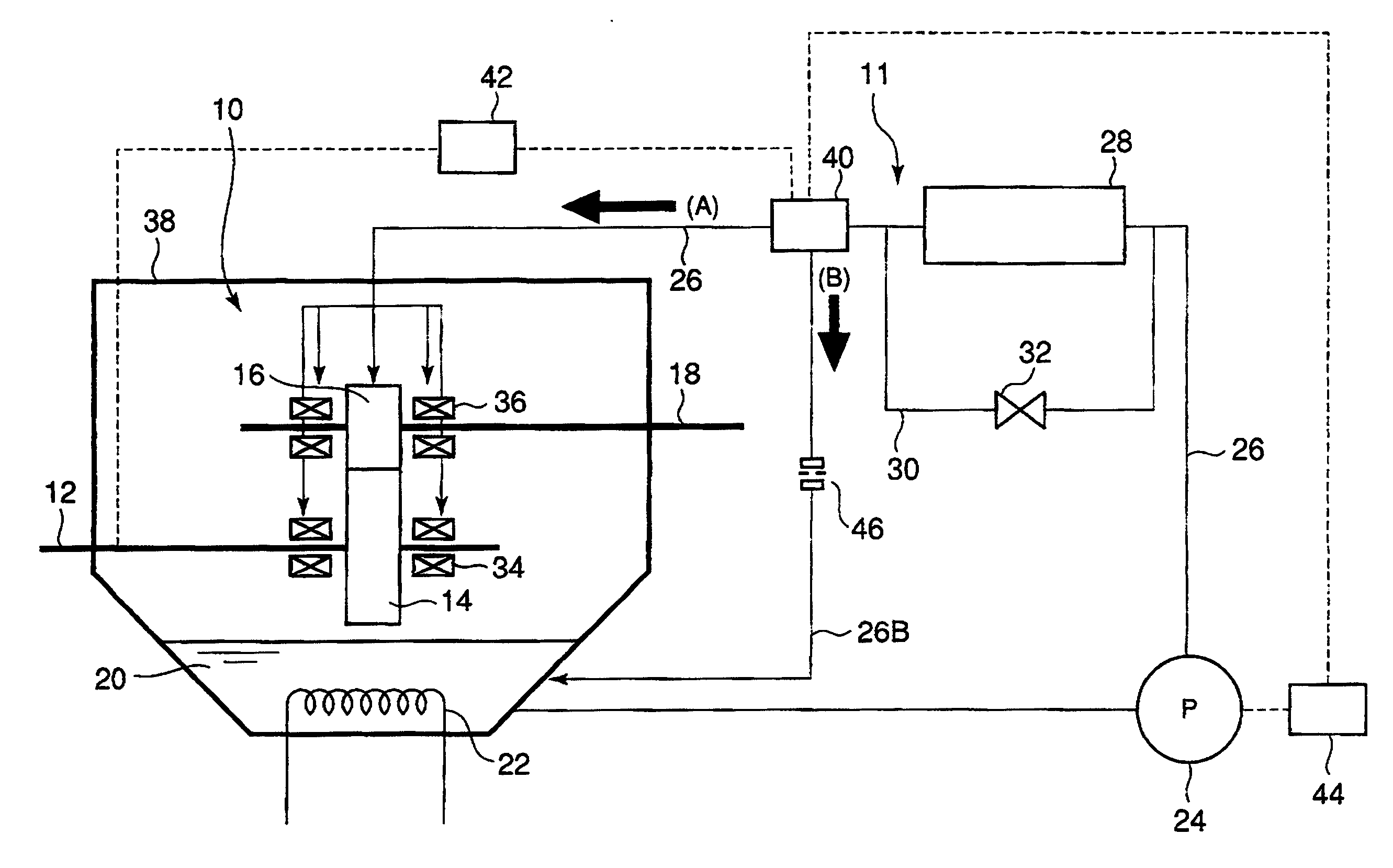
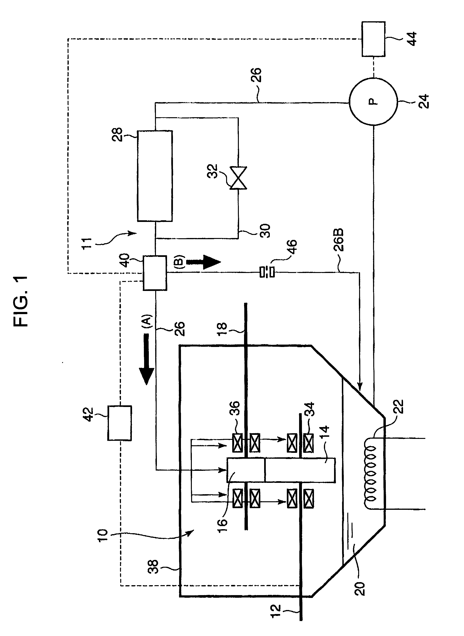
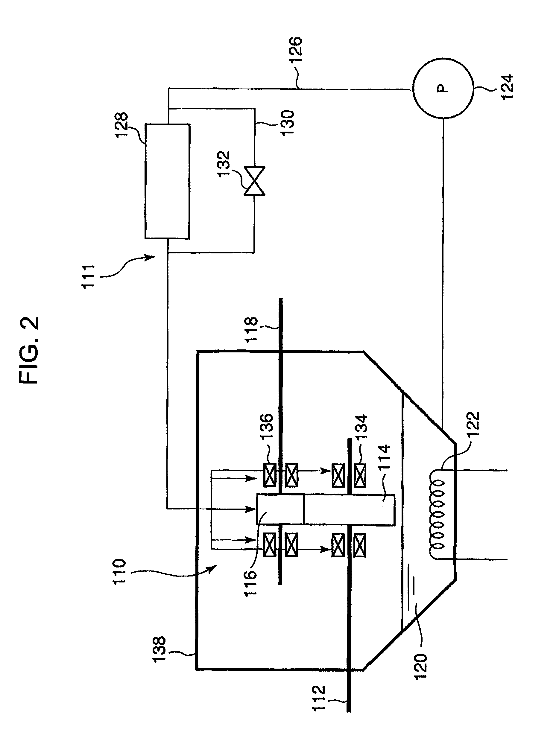
[0046]The tower 58 supports the nacelle 52 free of yawing and the nacelle 52 supports pivotally the hub 54 via a main shaft 12 being connected to the hub 54. One end of the main shaft 12 extends out of the nacelle 52 and the hub 54 is fixed to the end of the main shaft so as to rotate together with the main shaft 12. The nacelle 52 houses a gearbox 10, a generator 60, the main shaft 12, an output shaft 18 and ancillary devices not shown in the drawings. In the gearbox 10, a lubricating device (not shown in FIG. 1 and FIG. 2) is pro...


PUM


Abstract

In order to provide a lubricating device and lubricating method for a gearbox which does not take long to heat the lubricant oil and prevents the aeration of the lubricant oil due to the splashing thereof during the activation of the gearbox, the present invention provides a lubricating device for a gearbox comprising: a gearbox which includes an input shaft, a group of gears rotated by the rotation of the input shaft, and an output shaft rotated by the rotation of the group of gears, the rotation of the input shaft being speeded up and outputted to the output shaft via the group of gears; an oil storage chamber which stores lubricant oil for lubricating the gearbox; a lubricant oil circulating line which includes a pump and through which the lubricant oil stored in the oil storage chamber is supplied to the gearbox by the pump and then returned to the oil storage chamber; a bypass line which is provided in the oil lubricant circulating line and bypasses the gearbox; and a switching valve which is provided in the oil lubricant circulating line and switches a supply path of the lubricant between supplying the lubricant oil to the gearbox and supplying the lubricant oil to the bypass line.

Description

BACKGROUND OF THE INVENTION[0001]1. Field of the Invention[0002]The present invention relates to a lubricating device and a lubricating method for a gearbox, especially for a gearbox used in cold climates.[0003]2. Description of the Related Art[0004]Traditionally, frequently used in many industries is a gearbox which comprises an input shaft, an input side gear being rotated by the rotation of the input shaft, and an output side gear meshed with the input side gear and being rotated by the rotation of the input shaft, and in which the rotation of the main shaft is speeded up and outputted to the output shaft via the input side gear and output side gear.[0005]For instance, in a wind turbine of a wind turbine generator, the wind turbine rotates a blade, the main shaft (input shaft) is rotated by the rotation of the blade, the rotation of the main shaft is sped up by the gearbox and transmitted to the output shaft connected to a generator so as to generate electricity.[0006]In this typ...

Claims


Application Information

Patent Timeline
IPC IPC(8): F16H57/04F16H57/02
CPCF03D11/0008F05B2260/4031F05B2260/85Y02E10/722F16H57/0434F16H57/0461F16N39/04F05B2260/98F03D80/70Y02E10/72
Inventor YANO, AKIHIKONODA, YOSHITOMOYUGE, ATSUSHIOKANO, YASUSHITAKAYANAGI, KAZUFUMI
Owner MITSUBISHI HEAVY IND LTD
Why Eureka
Try Eureka