Eureka AIR delivers breakthrough ideas for toughest innovation challenges, trusted by R&D personnel around the world.

Swirl spraying nozzle for sprayng liquid fuel, and method of producing same, and a nozzle assembly for a burner with the swirl spraying nozzle

Inactive Publication Date: 2011-02-03
SIEMENS AG
View PDF5 Cites 1 Cited by
  • Summary
  • Abstract
  • Description
  • Claims
  • Application Information

AI Technical Summary

Benefits of technology

[0006]An object of the invention is to provide a swirl atomizing nozzle for atomizing liquid fuel, a method for producing the swirl atomizing nozzle, and a nozzle assembly for a gas turbine burner having the swirl atomizing nozzle, wherein the swirl atomizing nozzle and nozzle assembly are able to be produced inexpensively and are effective in terms of atomizing the liquid fuel.

Problems solved by technology

A conventional atomizing nozzle having swirl production is turned, milled and / or drilled from a complete material or alternatively produced having a micro-laminate design, which is expensive.

Method used


Image

  • Swirl spraying nozzle for sprayng liquid fuel, and method of producing same, and a nozzle assembly for a burner with the swirl spraying nozzle
  • Swirl spraying nozzle for sprayng liquid fuel, and method of producing same, and a nozzle assembly for a burner with the swirl spraying nozzle
  • Swirl spraying nozzle for sprayng liquid fuel, and method of producing same, and a nozzle assembly for a burner with the swirl spraying nozzle

Examples


Embodiment Construction

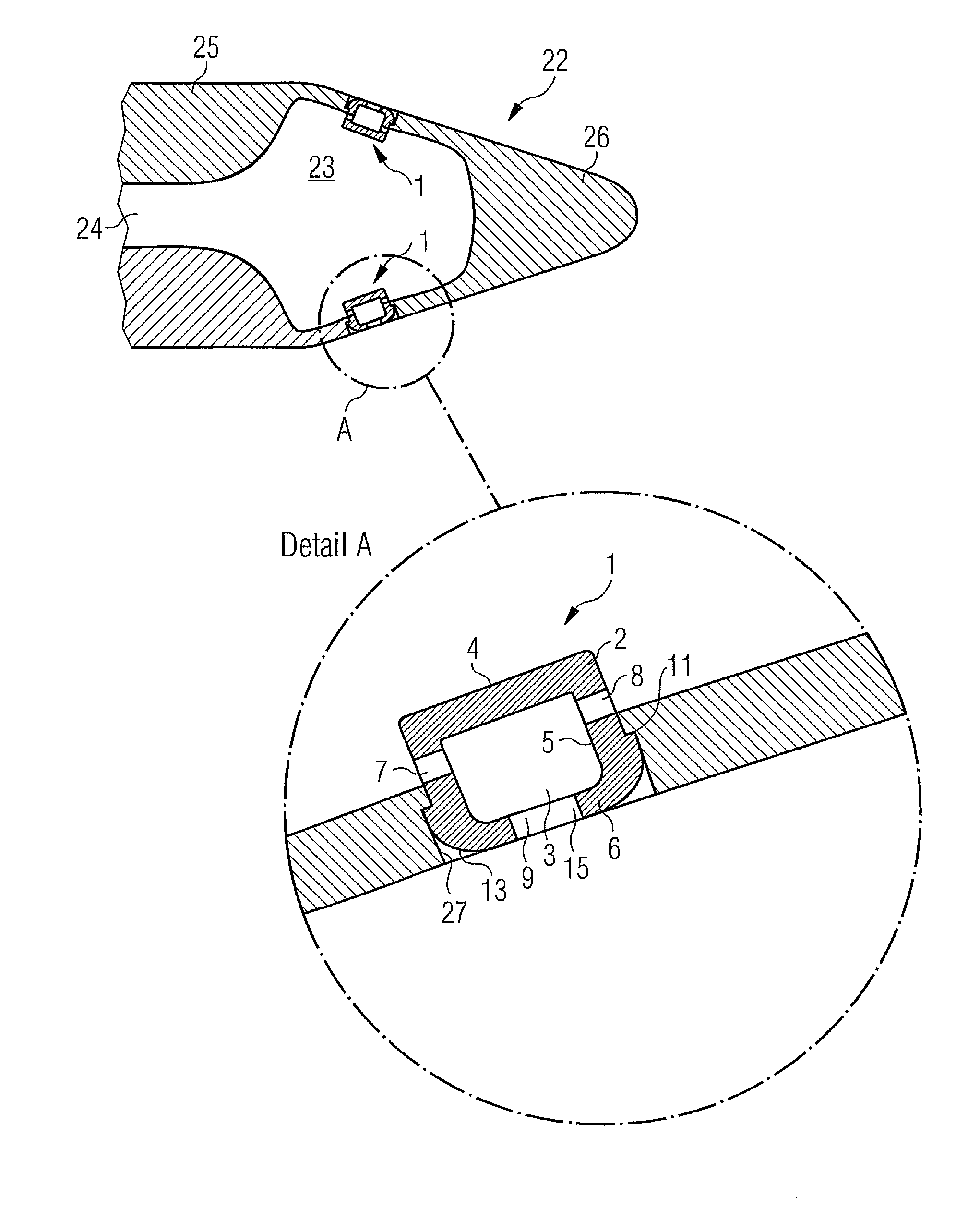
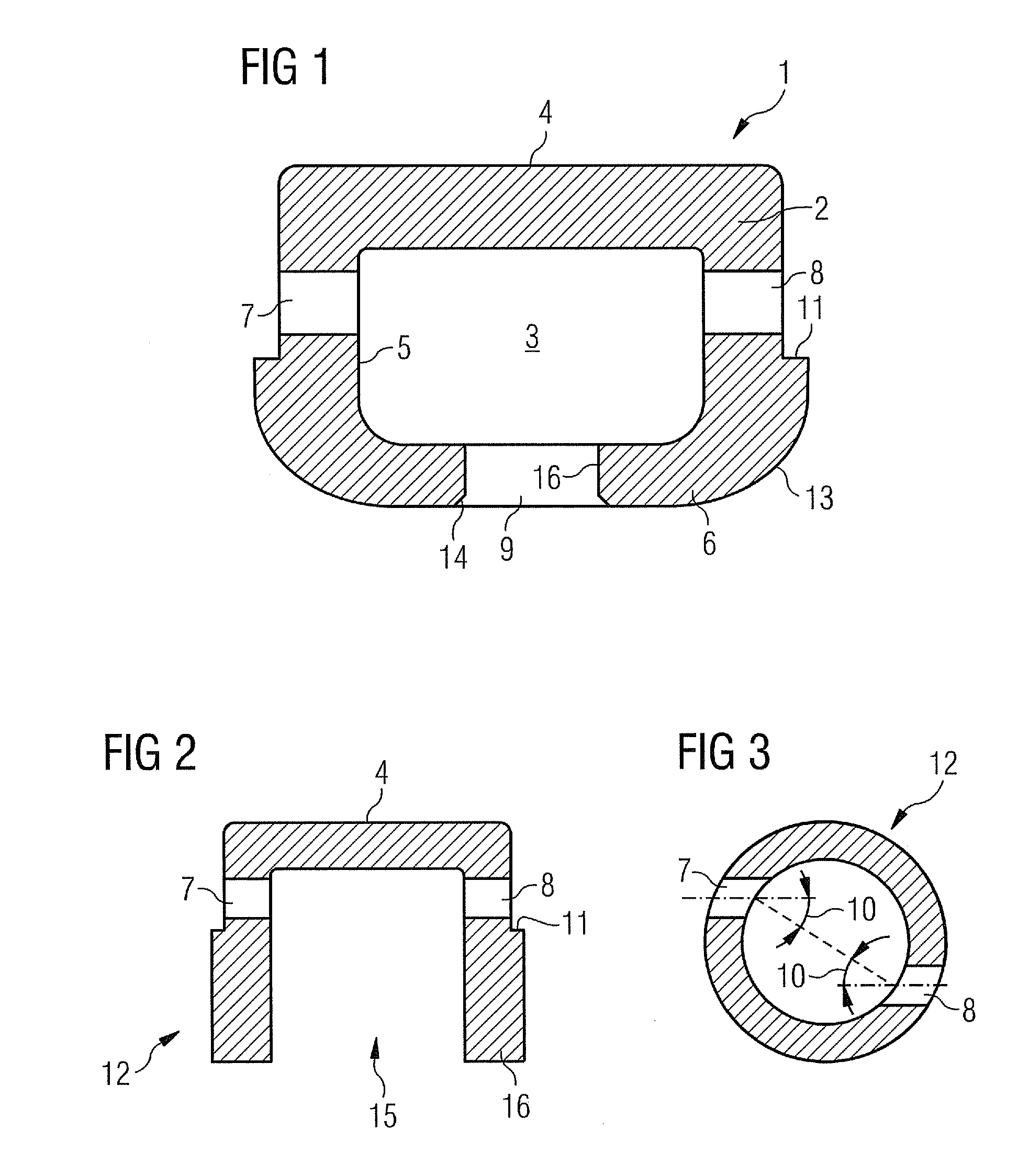
[0030]As can be seen in FIG. 1, a swirl atomizing nozzle 1 has a nozzle body 2 formed from a hollow cylinder 5 terminated by a base 4 at one end and a head 6 at the other. A swirl chamber 3 is thereby formed from the hollow cylinder 5, the base 4, and the head 6. Embodied in the hollow cylinder 5 in the region of the base 4 leading into the swirl chamber 3 is a first admission hole 7 and a second admission hole 8 (see FIG. 3). The admission holes 7, 8 lie in a plane that is perpendicular to the longitudinal axis of the hollow cylinder 5 and in which the admission holes 7, 8 are positioned circumferentially in the hollow cylinder 5 at a pitch 10 in the same direction. The admission holes 7, 8 are furthermore arranged point-symmetrically around the longitudinal axis of the hollow cylinder 5, with the longitudinal axes of the admission holes 7, 8 being mutually parallel. The admission holes 7, 8 thereby lead tangentially into the swirl chamber 3 and are arranged mutually opposite so th...


PUM


Abstract

A swirl spraying nozzle for spraying liquid fuel is provided. The swirl spraying nozzle includes a nozzle body including a hollow cylinder with a base terminating the hollow cylinder on one side and with a head terminating the hollow cylinder on the other side such that a swirl chamber is formed in the nozzle body. An admission hole is provided in the hollow cylinder in the vicinity of the base and is arranged in a plane perpendicular to the longitudinal axis of the hollow cylinder. The admission hole is positioned at an angle in the circumferential direction of the hollow cylinder. An outlet hole is provided in the head on the longitudinal axis of the hollow cylinder such that a liquid can flow tangentially through the admission hole with a swirling action into the swirl chamber and can flow out axially from the swirl chamber through the outlet opening.

Description

CROSS REFERENCE TO RELATED APPLICATIONS[0001]This application is the US National Stage of International Application No. PCT / EP2009 / 053361 filed Mar. 23, 2009, and claims the benefit thereof. The International Application claims the benefits of European Application No. 08006681.4 EP filed Apr. 1, 2008. All of the applications are incorporated by reference herein in their entirety.FIELD OF INVENTION[0002]The invention relates to a swirl atomizing nozzle for atomizing liquid fuel, a method for producing the swirl atomizing nozzle, and a nozzle assembly for a combustion chamber, in particular for a gas turbine, having the swirl atomizing nozzle.BACKGROUND OF INVENTION[0003]A gas turbine comprises a compressor, a combustion chamber and a turbine. A combustion air / fuel mixture is made to ignite in the combustion chamber, resulting in a stream of heating gas. The stream of heating gas is expanded in the turbine which drives the compressor and makes useful power available. The useful power ...

Claims


Application Information

Patent Timeline
IPC IPC(8): B05B1/34
CPCB21K21/14F23D11/383F23D11/103
Inventor HEILOS, ANDREASSCHNEIDER, OLIVER
Owner SIEMENS AG
Why Eureka
Eureka Blog
Learn More