Arc resistance performance evaluation device, arc resistance performance evaluation system, and arc resistance performance evaluation method

Inactive Publication Date: 2013-09-19
KANEKA CORP
View PDF4 Cites 0 Cited by
  • Summary
  • Abstract
  • Description
  • Claims
  • Application Information

AI Technical Summary

Benefits of technology

The present device uses a low voltage to achieve plasma input, which eliminates the need for high voltage and reduces the cost of the device. It also ensures stable and cost-effective irradiation with thermal plasma without the instability that can result from using arc discharge. The configuration of the present invention allows for stable and cost-effective irradiation with thermal flux under the same condition for evaluating arc resistance performance without using unstable arc.

Problems solved by technology

However, this method is not appropriate as a method for evaluating the arc resistance performance with respect to the fiber material to find the fiber material to be used for the clothing fabric for the following reasons.

Method used


Image

  • Arc resistance performance evaluation device, arc resistance performance evaluation system, and arc resistance performance evaluation method
  • Arc resistance performance evaluation device, arc resistance performance evaluation system, and arc resistance performance evaluation method
  • Arc resistance performance evaluation device, arc resistance performance evaluation system, and arc resistance performance evaluation method

Examples


examples

[0099]A method for actually evaluating the arc resistance performance using the present device 5 (present system 1) will be described with reference to the examples.

experiment conditions

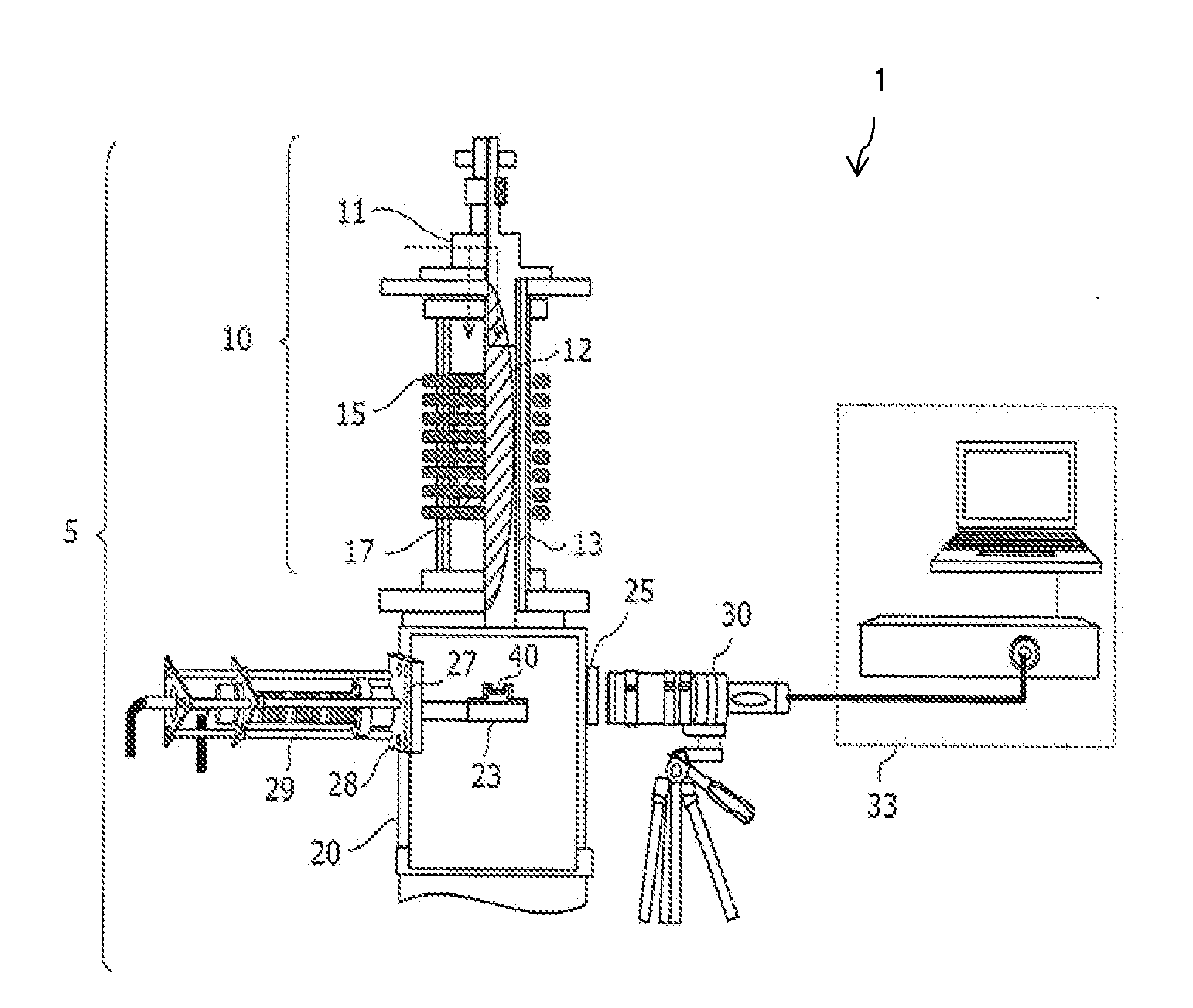
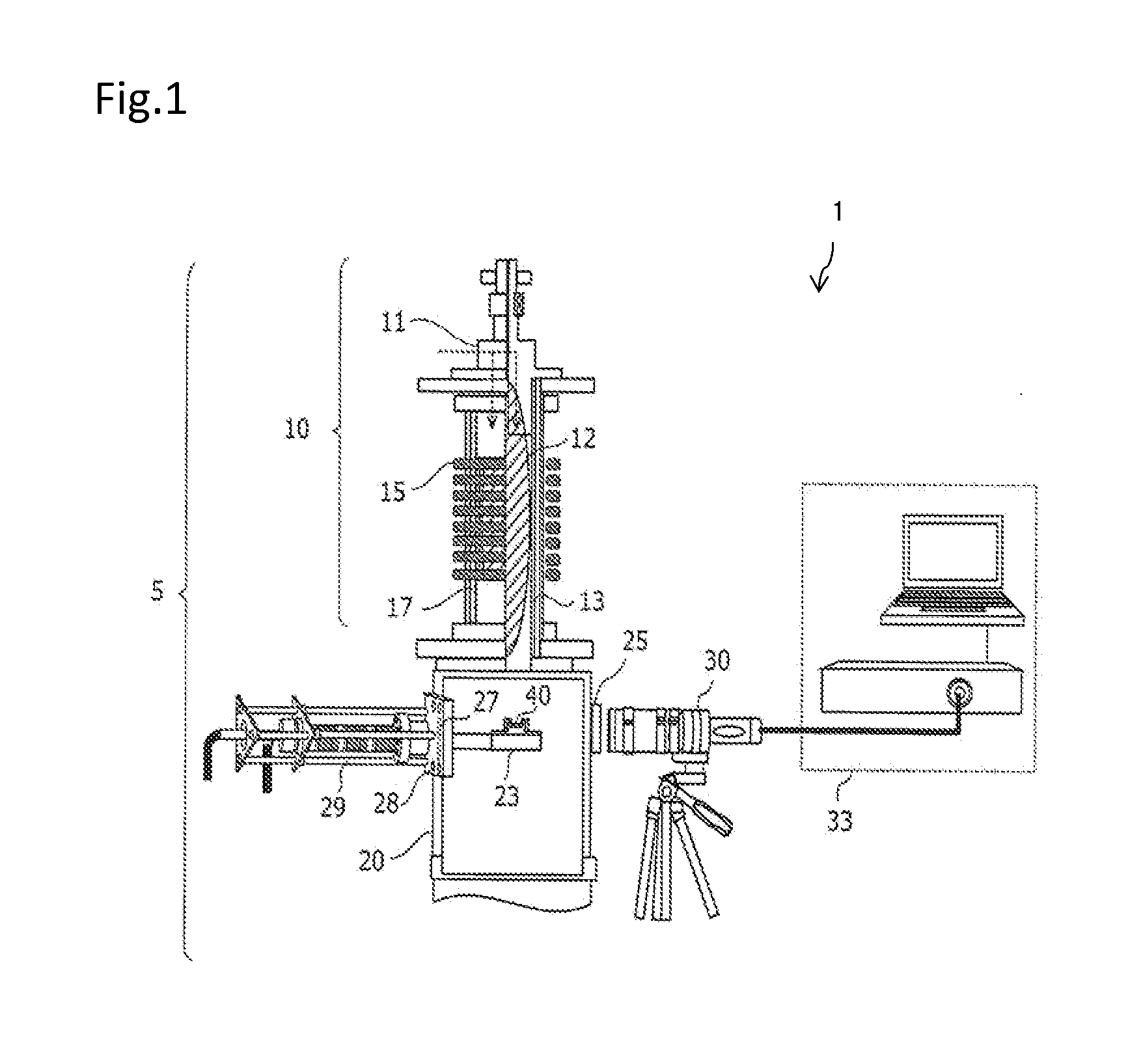
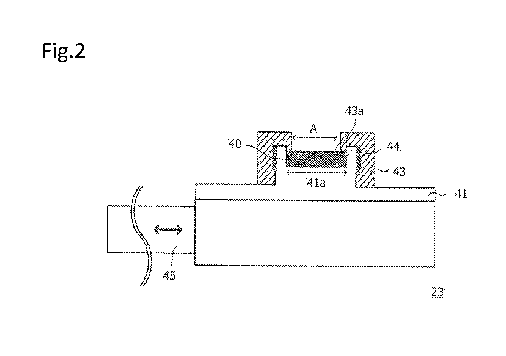
[0100]A double tube structure of a cylindrical quartz tube having an inner diameter of 70 mmφ, an outer diameter of 95 mmφ, and a length of 330 mm was adopted for the first tube portion 13. The testing subject installing pedestal 23 was set at a position 200 mm on the lower side of the induction coil 15. The induction coil 15 had eight turns.

[0101]The diameter of the conductor of the induction coil 15 is 14 mm. The induction coil 15 is formed by winding the conductor in a spiral form. The distance from the upper end to the lower end of the induction coil 15 is 155 mm, and the outer diameter of the induction coil is 132 mm.

[0102]Assuming Ar is the sheath gas, the plasma input power was set to 8.54 kW (corresponding to thermal flux of about 550 kW / m2), the sheath gas flow rate was set to 30 slpm, and the pressure in the first tube portion 13 was set to the atmospheric pressure (760 Torr).

[0103]The sheath gas adopts the external radius gas and the external rotation gas. The external ra...

example 1

[0109]In the example 1, the fiber material of acryl-vinylidene chloride copolymerization system expressed with the chemical formula [—(C3H3N)2—(C2H2Cl2)m—]n was used for the testing subject 40. This material is known by the name Kanecaron (manufactured by Kaneka Corporation, and registered trademark of Kaneka Corporation).


PUM


Abstract

The present device includes a high frequency induction thermal plasma generation unit 10; a second tube portion 20, which is connected to a first tube portion 13 and which includes window 25 on at least one side surface; and a testing subject installing pedestal 23 configured to be fixedly attached at a reference position in the second tube portion 20, wherein the testing subject installing pedestal 23 includes a seating portion for installing the testing subject 40, and a hold-down portion for fixing the installed testing subject 40 with a part of the testing subject exposed; and an ablated vapor generated from the testing subject is observed through the window from an outer side of the second tube portion.

Description

BACKGROUND OF THE INVENTION[0001]This application claims priority under 35 U.S.C. §119(a) on Japanese Patent Application No. 2012-060734 filed in Japan on Mar. 16, 2012, the entire contents of which are hereby incorporated by reference.[0002]A part of the present invention is disclosed by inventors at study meetings below.[0003](1) ISHIDA Masahiro et al., “Ablated phenomenon from Polymer Fibers Irradiated by Ar Thermal Plasmas.”, 2011 Joint Conference of Hokuriku Chapters of Electrical Societies, Date of Presentation; Sep. 17, 2011, Date of distribution of CD-ROM; Sep. 17, 2011.[0004](2) ISHIDA Masahiro et al., “Irradiated test of Ar, Ar+O2 and Ar+N2 thermal plasmas to flame retardant fibers.”, 2011 Joint Symposium on Electrical Discharge, Switch Protection and High Voltage Engineering of the Institute of Electrical Engineers of Japan, Date of Presentation; Nov. 10, 2011, Date of distribution of pamphlet; Nov. 10, 2011.[0005](3) ISHIDA Masahiro et al., “Estimation on Composition and...

Claims


Application Information

Patent Timeline
IPC IPC(8): G01N27/04
CPCG01N33/367G01N27/04
Inventor TANAKA, YASUNORIISHIDA, MASAHIROSHINSEI, NAOKIHAGI, HIROYASUMIZOBUCHI, ATSUSHI
Owner KANEKA CORP
Why Eureka
Try Eureka