

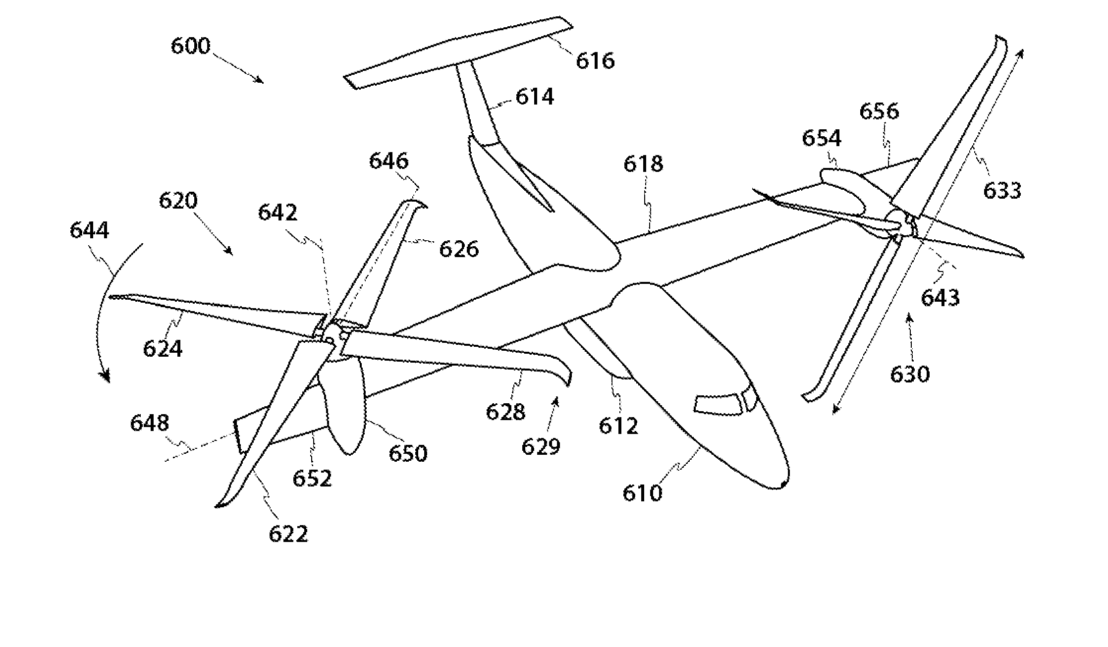
Anhedral Tip Blades for Tiltrotor Aircraft
a technology of anhedral tip and tilt-rotor aircraft, which is applied in the direction of vertical landing/take-off aircraft, aircraft navigation control, transportation and packaging, etc., can solve the problems of increased drag, reduced performance from increased induced losses, and all prior art methods have limited effects
- Summary
- Abstract
- Description
- Claims
- Application Information
AI Technical Summary
Benefits of technology
Problems solved by technology
Method used
Image

Examples
Embodiment Construction
[0029]The detailed description that follows describes key method and system aspects of the inventive subject matter. It is an object of the following description to show that specially shaped blade tips for tiltrotors can improve hover performance by altering wake trajectory at the expense of reduced edgewise rotor performance.
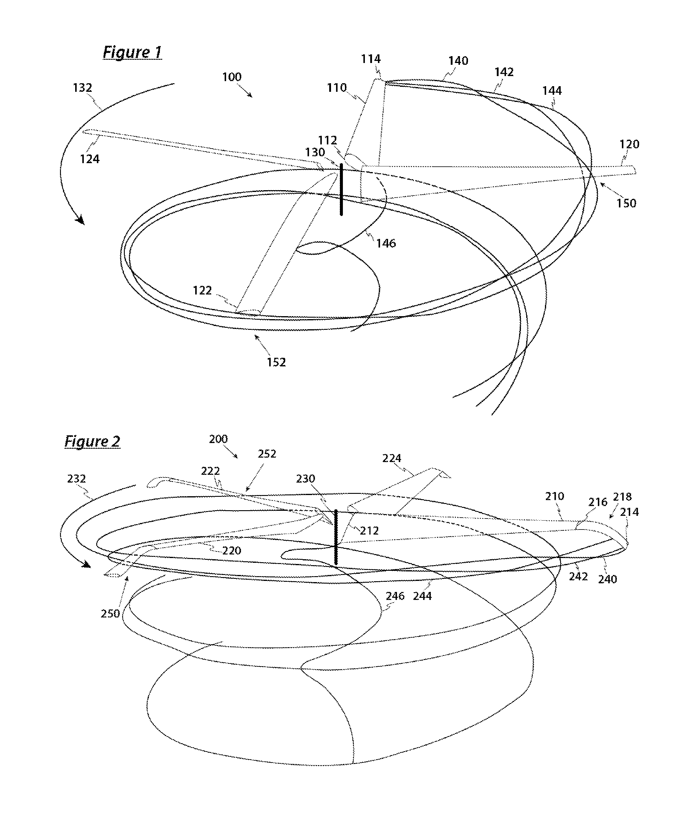
[0030]FIG. 1 is a perspective illustration of an isolated rotor in hover with straight blades and conventional blade tips trailing a helical vortex wake. FIG. 1 is drawn with the aid of the CHARM (Comprehensive Hierarchical Aeromechanics Rotorcraft Model) computer code, produced by Continuum Dynamics, Inc. and described in the 2003 paper “First-Principles Free-Vortex Wake Analysis for Helicopters and Tiltrotors”, presented at the Presented at the American Helicopter Society 59th Annual Forum in Phoenix, Ariz. CHARM is generally regarded by the industry as among the leading and most accurate methods for calculating rotor performance and rotor wake structures.
[0...
PUM
 Abstract
Description
Claims
Application Information