Vertical take-off and landing aircraft with distributed power unit configuration

A power plant, vertical take-off and landing technology, applied in vertical take-off and landing aircraft, unmanned aerial vehicles, aircraft and other directions, can solve the problems of low flight speed, complex and huge body structure, complex rotor system, etc., to achieve high control efficiency, High propulsion efficiency and good wind resistance

Inactive Publication Date: 2016-12-14
杭州迅蚁网络科技有限公司
View PDF6 Cites 18 Cited by
  • Summary
  • Abstract
  • Description
  • Claims
  • Application Information

AI Technical Summary

Problems solved by technology

[0005] The invention provides a vertical take-off and landing aircraft with a distributed power device layout, aiming

Method used


Image

  • Vertical take-off and landing aircraft with distributed power unit configuration
  • Vertical take-off and landing aircraft with distributed power unit configuration

Examples


Embodiment 1

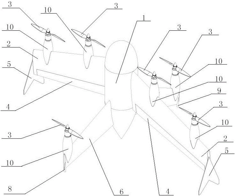
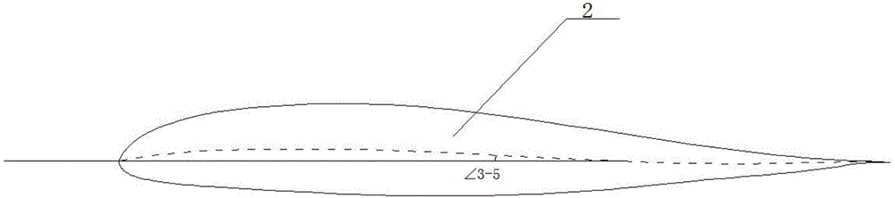
[0025] A vertical take-off and landing aircraft with a distributed power plant layout, such as figure 1 As shown, the vertical take-off and landing aircraft includes a fuselage 1, and two left and right wings 2 are symmetrically arranged on both sides of the fuselage. In the embodiment, it can be called the left wing and the right wing, but the left and right are not protected here Restricted, the tail of each wing 2 is provided with an empennage, and a propeller 3 is arranged at the upper end of the wing 2. The fuselage 1 adopts a semi-monocoque structure. The fuselage 1 has three parts: including the nose, the middle section and the tail, and the fuselage 1 The middle section is used as a cargo compartment, and left and right symmetrical wings 2 are arranged on both sides of the fuselage 1, and an elevon 4 is arranged at the tail of each wing 2, and the elevon 4 is hinged on the wing by means of hinges. The trailing edge of 2 can simultaneously realize the main control surfa...

Embodiment 2

[0027] Embodiment 2 (this embodiment does not have schematic diagram):

[0028] A vertical take-off and landing aircraft with a distributed power plant layout. The vertical take-off and landing aircraft includes a fuselage 1, and two left and right wings 2 are symmetrically arranged on both sides of the fuselage 1. In the embodiment, it can be called the left wing and the right wing. Wings, but the scope of protection is not limited here. The tail of each wing 2 is provided with an empennage, and the upper end of the wing 2 is provided with a propeller 3. In this embodiment, the fuselage 1 adopts a semi-monocoque structure , the fuselage 1 has three parts: the nose, the middle section and the tail. The middle section of the fuselage 1 is used as a cargo compartment. 1. Left and right symmetrical wings 2 are arranged on both sides, and an elevon 4 is arranged at the tail of each wing 2. The elevon 4 is hinged to the trailing edge of the wing 2 by means of a hinge and can simult...


PUM


Abstract

The invention discloses a vertical take-off and landing aircraft with distributed power unit configuration. The vertical take-off and landing aircraft with the distributed power unit configuration comprises an aircraft body, aircraft wings, an empennage and propellers. The aircraft body is of a semi-monocoque structure, and comprises a nose, a middle fuselage and an aircraft tail. The middle fuselage of the aircraft body is a cargo bay. The aircraft wings are arranged on the two sides of the aircraft body in a left-right symmetry mode. The aircraft wings are of double-beam semi-monocoque structures and connected with the aircraft body through reinforced frames. Auxiliary lifting wings are arranged at the rear edges of the aircraft wings correspondingly. End-plate type winglets are arranged at the wingtips of the aircraft wings correspondingly. According to the vertical take-off and landing aircraft with the distributed power unit configuration, the distributed propelling unit configuration is adopted, so that the aircraft can have a low rotor disk load and the high propelling efficiency during the vertical take-off and landing processes; a combined control mode combining the motor rotating speed/ the propeller pitch with a propeller slip flow rudder is adopted, so that the control efficacy is high; tailless flying wing configuration is adopted for a fixed wing face, the size of the aircraft is decreased, the structure is more compact and easy to detach and maintain, and the wind resistance is good in the vertical take-off and landing stages compared with conventional configuration and a canard configuration.

Description

technical field [0001] The invention relates to a micro-aircraft, in particular to a vertical take-off and landing aircraft with a distributed power device layout. Background technique [0002] Vertical take-off and landing aircraft usually include helicopters, rotorcraft, flapping wing aircraft, tilting rotor aircraft, tail seat vertical take-off and landing aircraft, and vertical take-off and landing aircraft equipped with lift fans or vector propulsion devices. The structure of the tail seat vertical take-off and landing aircraft is simple, and the vertical flight and the horizontal flight use the same power system fixed to the body, which has high reliability and does not have the waste weight caused by multiple power systems. [0003] The vertical take-off and landing aircraft can be summarized as follows: traditional helicopters have low flying speed, short range, and complex rotor system; when adding tilting propellers / tilting rotors, compared with traditional helicop...

Claims


Application Information

Patent Timeline
IPC IPC(8): B64C29/02B64C27/08B64C27/26
CPCB64C27/08B64C27/26B64C29/02B64U30/10B64U30/20
Inventor 章磊吴大卫
Owner 杭州迅蚁网络科技有限公司
Why Eureka
Try Eureka