
Apparatus having a screened structure for detecting thermal radiation

a technology of thermal radiation and apparatus, applied in electrical apparatus, radiation pyrometry, instruments, etc., can solve the problems of large space requirement of device b>300/b>, complicated and cost-intensive manufacture of device b>300/b>, and the fashion of hermetically sealed bonding connection b>333/b>

Inactive Publication Date: 2011-02-03
PERLOS OY
View PDF4 Cites 0 Cited by
  • Summary
  • Abstract
  • Description
  • Claims
  • Application Information

AI Technical Summary

Benefits of technology

[0009]An object of the invention is to provide a device for detection of thermal radiation that exhibits a lower space requirement in comparison to the prior art and can be manufactured simply and cost-effectively.

Problems solved by technology

However, it is disadvantageous that the device 300 has a large space requirement due to the large structural height of the protective housing 330.
Both the insertion and sealing of the glass window 331 in the window opening 334 and the fashioning of the hermetically sealed bonding connection 333 in the manufacture of the device 300 are also complicated and cost-intensive.
However, this entails a significant space requirement for a wiring of the detector elements, with the result of a limited, relatively low detector element density (number of detector elements per surface segment of the detector substrate).

Method used


Image

  • Apparatus having a screened structure for detecting thermal radiation
  • Apparatus having a screened structure for detecting thermal radiation
  • Apparatus having a screened structure for detecting thermal radiation

Examples


Embodiment Construction

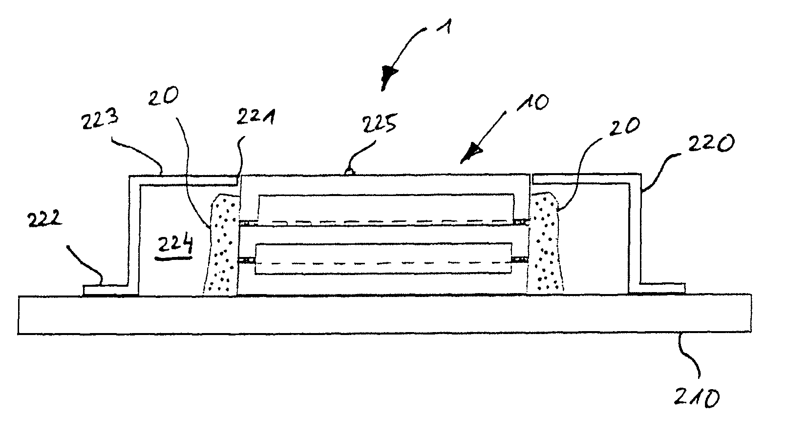
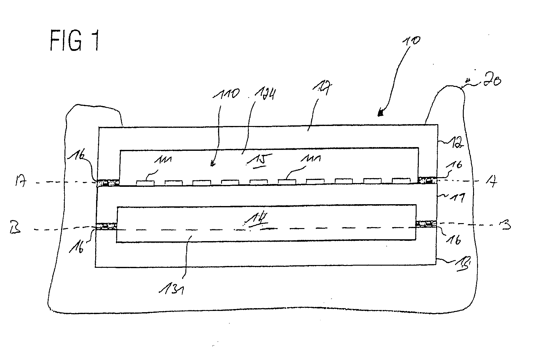
[0050]As is apparent from FIGS. 1 through 6, a device for the detection of thermal radiation possesses a substrate 210 on which is arranged a stack 10. The stack 10 possesses a stack top side 225 facing away from the substrate 210 and is attached to the substrate 210 by means of a casting compound 20.

[0051]The device 1 also has a protective housing 220 in which the stack 10 is housed. The protective housing 220 is produced from metal so that the stack 10 is electromagnetically externally shielded by the protective housing 220.

[0052]The protective housing 220 has a top side 223 that is arranged facing away from the substrate 210. An opening 221 in which the stack 10 engages with its top side 225 is provided in the top side 223, such that the top side 223 of the protective housing 220 and the top side 225 of the stack 10 terminate level with one another.

[0053]The peripheral contour of the opening 221 is also fashioned such that, on the stack top side 225, the stack 10 is adjacent to t...


PUM


Abstract

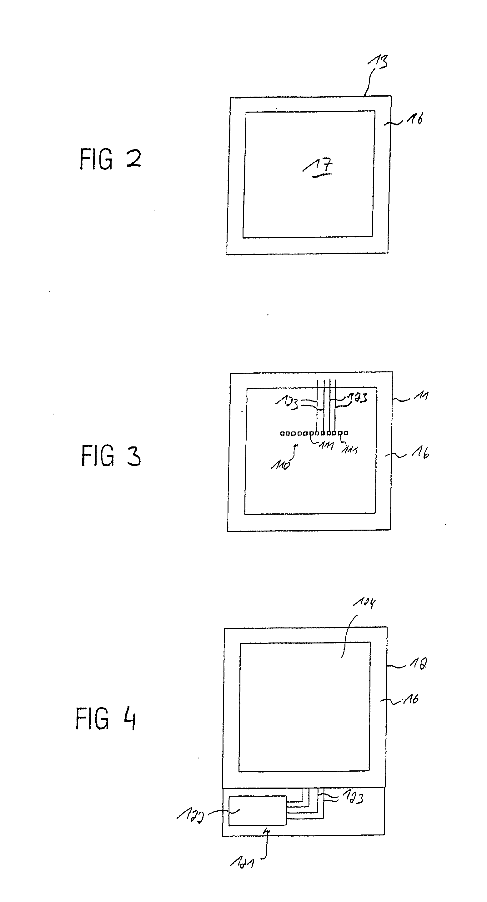
An apparatus for detecting radiation has a substrate, a protective housing fitting on the substrate, which has an electrically conductive material and a top facing away from the substrate, and that has an aperture therein. A stack is fitted on the substrate inside the protective housing and includes at least one detector substrate having at least one thermal detector element thereon that converts incoming thermal radiation into an electrical signal, at least one circuit carrier having at least one read circuit for reading out the electrical signal, and at least one cover that covers the detector element. The detector substrate is located between the circuit substrate and the cover. The detector substrate and the cover are arranged on each other such that the detector element of the detector substrate and the cover have at least one first stack cavity of the stack therebetween, the stack cavity being defined by the detector support and the cover. The circuit substrate and the detector substrate are arranged on each other such that the detector substrate and the circuit substrate have at least one second stack cavity therebetween, the second stack cavity being defined by the circuit substrate and the detector substrate. At least one of the first stack cavity and the second stack cavity is evacuated. The stack top that faces the substrate is accessible from outside of the protective housing.

Description

BACKGROUND OF THE INVENTION[0001]1. Field of the Invention[0002]The invention concerns a device to detect thermal radiation with at least one shielded thermal detector element to transduce the thermal radiation into an electrical signal. In addition to the device a use of the device is specified.[0003]2. Description of the Prior Art[0004]A conventional device 300 for detection of thermal radiation is shown in FIG. 7. The device 300 has a substrate 310 and a sensor 320 that is attached to the substrate 310 by means of a casting compound 312. The device 300 also has a protective housing 330 that is arranged over the sensor 320 and attached to the substrate 310 by means of a hermetically sealed bonding connection 333. The protective housing 330 is dimensioned such that said protective housing 330 does not directly contact the sensor 320, such that an inner space 335 is fashioned between the sensor 320 and the protective housing 330. The protective housing 330 has a top side 332 that is...

Claims


Application Information

Patent Timeline
IPC IPC(8): H01L31/0203
CPCG01J5/0285H01L27/14618G01J5/045G01J5/04H01L2924/0002G01J5/068H01L2924/00
Inventor WRIGHT, JEFFREY
Owner PERLOS OY
Learn More